
Signal transmission method and device

A signal transmission and signal technology, applied in the field of communication, can solve the problems of reducing the transmission quality of uplink control signals, reducing the maximum power, etc.

Active Publication Date: 2021-01-29
BEIJING XIAOMI MOBILE SOFTWARE CO LTD
View PDF3 Cites 0 Cited by
  • Summary
  • Abstract
  • Description
  • Claims
  • Application Information

AI Technical Summary

Problems solved by technology

[0004] However, when the user terminal uses different scheduling cycles and transmission durations for data of different service types, it will result in the situation that PUCCH signals with different transmission durations and different transmission formats need to be transmitted at the same time. For this situation, if the user terminal Simultaneous transmission of multiple PUCCH signals distributed on different frequency resources will result in larger PAPR (Peak-to-Average Power Ratio, peak-to-average power ratio) and MPR (Maximum power reduction, maximum power reduction), reducing the Transmission quality of uplink control signals

Method used


Image

  • Signal transmission method and device
  • Signal transmission method and device
  • Signal transmission method and device

Examples


Embodiment Construction

[0127] Reference will now be made in detail to the exemplary embodiments, examples of which are illustrated in the accompanying drawings. When the following description refers to the accompanying drawings, the same numerals in different drawings refer to the same or similar elements unless otherwise indicated. The implementations described in the following exemplary examples do not represent all implementations consistent with the present invention. Rather, they are merely examples of apparatuses and methods consistent with aspects of the invention as recited in the appended claims.

[0128] The terminology used in the present disclosure is for the purpose of describing particular embodiments only, and is not intended to limit the present disclosure. As used in this disclosure and the appended claims, the singular forms "a", "the", and "the" are intended to include the plural forms as well, unless the context clearly dictates otherwise. It should also be understood that the ...


PUM


Abstract

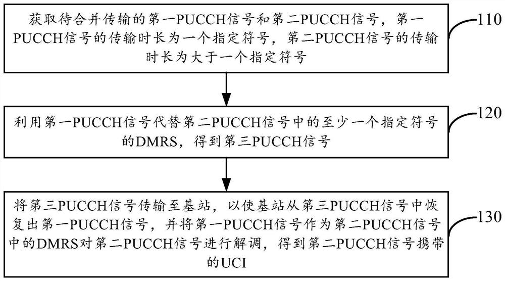
The present disclosure provides a signal transmission method and device. The method is used in a terminal, including obtaining a first PUCCH signal and a second PUCCH signal. The transmission duration of the first PUCCH signal is a specified symbol, and the transmission duration of the second PUCCH signal is Greater than one specified symbol; using the first PUCCH signal to replace the DMRS of at least one specified symbol in the second PUCCH signal to obtain a third PUCCH signal; transmitting the third PUCCH signal to the base station so that the base station recovers from the third PUCCH signal The first PUCCH signal, using the first PUCCH signal as a DMRS in the second PUCCH signal to demodulate the second PUCCH signal, to obtain the UCI carried by the second PUCCH signal. Therefore, the present disclosure can solve the transmission conflict problem that occurs when the terminal simultaneously transmits PUCCH signals with different transmission durations.

Description

technical field [0001] The present disclosure relates to the field of communication technologies, and in particular, to a signal transmission method and device. Background technique [0002] In the new-generation communication system, it is necessary to support flexible configuration of various types of services. Moreover, different service types correspond to different requirements. For example, the main requirements of the eMBB (enhanced Mobile Broad Band, enhanced mobile broadband) service type focus on large bandwidth and high speed; the main requirements of the URLLC (Ultra Reliable Low Latency Communication, high reliability and low delay communication) In terms of high reliability and low delay; mMTC (massive Machine Type Communication, massive machine type communication) business type mainly requires a large number of connections. [0003] In related technologies, when a user terminal runs an eMBB-type service and a URLLC-type service at the same time, the terminal...

Claims


Application Information

Patent Timeline
Patent Type & Authority Patents(China)
IPC IPC(8): H04L5/00H04W72/12
CPCH04L5/0007H04L5/0042H04L5/0048H04L5/0053H04W72/21H04L5/0051H04L5/0094H04L5/10H04L27/2605
Inventor 赵群朱亚军张明
Owner BEIJING XIAOMI MOBILE SOFTWARE CO LTD
Learn More