Laser welding equipment

A technology of laser welding and equipment, applied in laser welding equipment, welding equipment, metal processing equipment, etc.

Pending Publication Date: 2018-08-24
BESITER CO LTD
View PDF0 Cites 7 Cited by
  • Summary
  • Abstract
  • Description
  • Claims
  • Application Information

AI Technical Summary

Problems solved by technology

[0004] The object of the present invention is to provide a kind of laser welding equipment, aim at solving the problem in the prior art, need to provide PVC plate and electric core for welding station

Method used


Image

  • Laser welding equipment
  • Laser welding equipment
  • Laser welding equipment

Examples


Embodiment approach

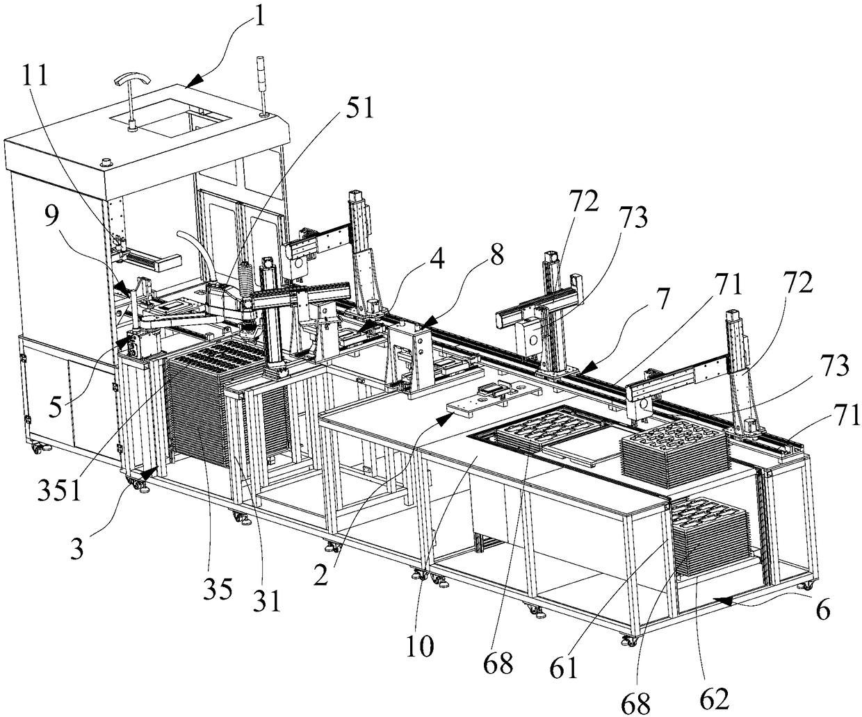
[0045] Further, see Figure 1-Figure 2 and Figure 4 As a specific implementation of the laser welding equipment provided by the present invention, the plate transfer device 5 includes a plate transfer manipulator 51, and a plate loading connecting plate 52 connected to the output end of the plate transfer manipulator 51 , The plate pneumatic finger 53 provided on the plate feeding connecting plate 52, and the CCD sensor 54 provided on the plate feeding connecting plate 52; the plate feeding device 3 includes the The plate supporting frame 31 connected to the platform 10, the plate loading lifting plate 32 slidably connected to the plate supporting frame 31 and used for placing the plate material tray 35, and used to drive the plate loading The lifting plate 32 moves up and down the plate feeding and lifting driving device. The plate feeding and lifting drive device includes a plate feeding screw nut connected to the plate feeding lifting plate 32, and a plate feeding screw sha...

specific Embodiment approach

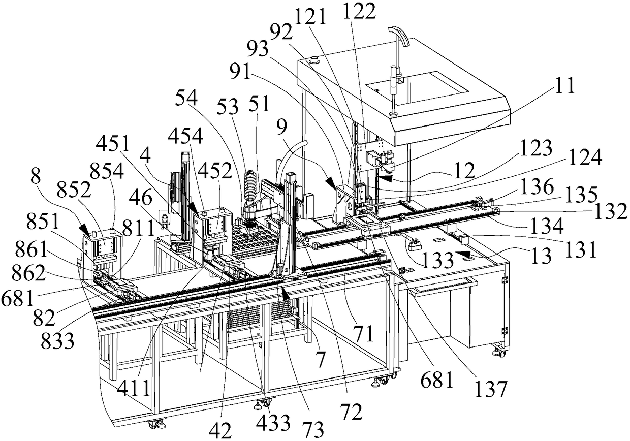
[0049] Further, see figure 2 As a specific implementation of the laser welding equipment provided by the present invention, the carrier drive mechanism 13 includes a first carrier slide 131, and a carrier slide 132 slidably connected to the first carrier slide 131 , A first carrier screw nut connected to the carrier sliding seat 132, a first carrier screw shaft 133 matched with the first carrier screw nut, for driving the first carrier The first carrier drive motor rotated by the screw shaft 133, the second carrier slide 134 provided on the carrier slide 132, the second carrier screw nut connected to the welding carrier 137, and The second carrier screw shaft 135 matched with the second carrier screw nut, and the second carrier drive motor 136 for driving the second carrier screw shaft 135 to rotate; the welding carrier 137 It is slidably connected to the second carrier rail 134, and the first carrier rail 131 and the second carrier rail 134 are perpendicular to each other. T...


PUM


Abstract

The invention discloses laser welding equipment. The laser welding equipment comprises a laser welding device, a supply platform, a plate loading device, a plate transfer device for transferring PVC plates in a plate tray to the laser welding device, an electric core loading device arranged on the supply platform, and an electric core transfer device; and the electric core transfer device comprises an electric core transfer slide rail, an electric core transfer manipulator, an electric core transfer slide driving device and a sucker module. The plate loading device conveys the plate tray to aposition near and leveled with the surface of the supply platform; the plate transfer device transfers the PVC plates in the plate tray to a position corresponding to the laser welding device; the electric core loading device conveys an electric core tray with electric cores to a position leveled with the surface of the supply platform; the electric core transfer device transfers the electric cores in the electric core tray to a position corresponding to the laser welding device; and at this time, the laser welding device starts to work to weld polar lugs of the electric cores and the PVC plates to realize provision of the PVC plates and the electric cores to a welding table.

Description

Technical field [0001] The invention relates to the field of welding equipment, in particular to laser welding equipment. Background technique [0002] The mobile power supply is a portable charger that integrates power supply and charging functions. It can charge mobile phones, tablet computers and other digital devices anytime and anywhere. Generally, a lithium battery cell is used as the power storage unit, which is convenient and quick to use. [0003] In the production process of mobile power supply, it is necessary to set a PVC board at the end of the battery. The tabs on the battery are welded to the conductive part on the PVC board. The battery is placed in the battery tray, and the PVC board is placed on the board. Pieces in the tray. In the welding process of the battery core and the PVC board, the PVC board and the battery need to be provided for the welding station at the same time. Summary of the invention [0004] The purpose of the present invention is to provide a...

Claims


Application Information

Patent Timeline
IPC IPC(8): B23K26/21B23K26/70
CPCB23K26/21B23K26/702
Inventor 潘良春
Owner BESITER CO LTD
Why Eureka
Try Eureka