Fault location method, device, equipment and medium based on traveling wave difference current

A technology of fault location and differential current, which can be used in measurement devices, fault locations, and fault detection according to conductor types, etc., and can solve the problems of high sampling rate identification and calibration of the traveling wave method.

Active Publication Date: 2020-05-08
ELECTRIC POWER RESEARCH INSTITUTE, CHINA SOUTHERN POWER GRID CO LTD +1
View PDF6 Cites 0 Cited by
  • Summary
  • Abstract
  • Description
  • Claims
  • Application Information

AI Technical Summary

Problems solved by technology

[0004] When the inventor implemented the embodiment of the present invention, he found that the prior art has the following defects: the traveling wave method itself has inherent problems such as requiring an ultra-high sampling rate and identification and calibration of the initial wave head and reflected traveling waves. The development of the

Method used


Image

  • Fault location method, device, equipment and medium based on traveling wave difference current
  • Fault location method, device, equipment and medium based on traveling wave difference current
  • Fault location method, device, equipment and medium based on traveling wave difference current

Examples


Embodiment 1

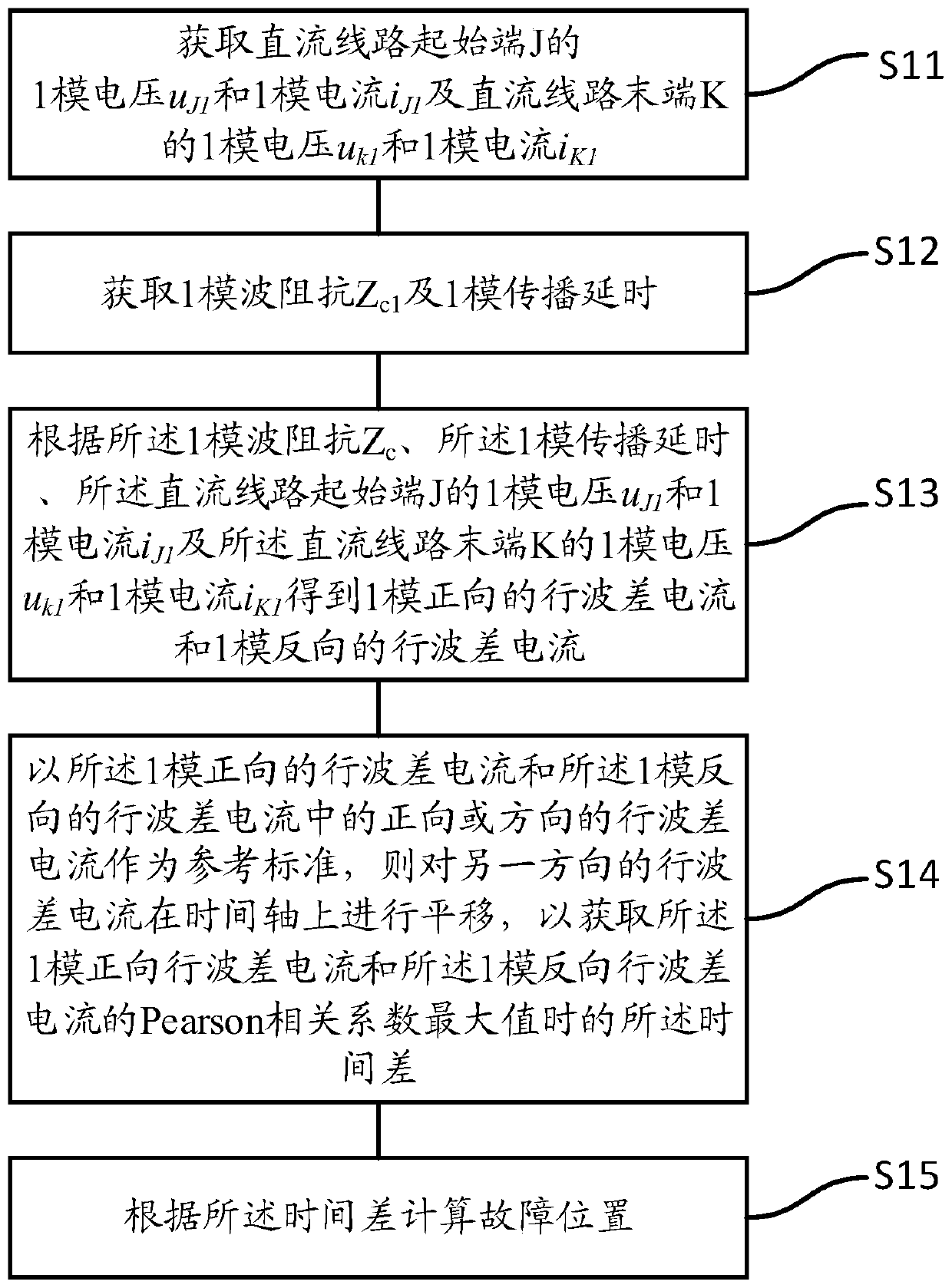
[0065] see figure 1 , a schematic flowchart of a fault location method based on traveling wave difference current provided in the first embodiment of the present invention;

[0066] S11. Acquiring the 1-mode voltage u of the starting end J of the DC line J1 and 1-mode current i J1 and the 1-mode voltage u at the terminal K of the DC line k1 and 1-mode current i K1 ;

[0067] Preferably, the acquisition of the 1-mode voltage u of the starting end J of the DC line J1 and 1-mode current i J1 and the 1-mode voltage u at the terminal K of the DC line k1 and 1-mode current i K1 include:

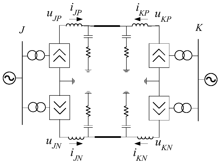
[0068] Obtain the positive voltage u of the starting terminal J of the DC line JP , Negative voltage u JN ;

[0069] Obtain the positive current i of the starting end J of the DC line JP , Negative current i JN ;

[0070] Obtain the positive voltage u of the starting end K of the DC line KP , Negative voltage u KN ;

[0071] Obtain the positive current i of the starting end K of th...

Embodiment 2

[0135] Embodiment two, on the basis of embodiment one, refer to Figure 5 It is a schematic flowchart of another fault location method based on traveling wave difference current provided by the second embodiment of the present invention; preferably, the traveling wave difference current with the 1-mode forward and the reverse traveling wave difference current of the 1-mode The positive or reverse traveling wave difference current in the middle is used as a reference standard, then the traveling wave difference current in the other direction is shifted on the time axis to obtain the 1-mode forward traveling wave difference current and the 1-mode reverse traveling wave difference current The time difference Δt at the time of the maximum value of the Pearson correlation coefficient includes:

[0136] S21. Select the time window after the fault as [t st ,t st +t w ] of the 1-mode reverse traveling wave difference current As a reference standard; where, the t w ≥2·τ 1 ...

Embodiment 3

[0147] Embodiment three, on the basis of embodiment one, refer to Image 6 It is a schematic flowchart of another fault location method based on traveling wave difference current provided by the third embodiment of the present invention;

[0148] Preferably, the traveling wave difference current in the 1-mode forward direction and the reverse traveling wave difference current of the 1-mode The positive or reverse traveling wave difference current in the middle is used as a reference standard, then the traveling wave difference current in the other direction is shifted on the time axis to obtain the 1-mode forward traveling wave difference current and the 1-mode reverse traveling wave difference current The time difference Δt at the time of the maximum value of the Pearson correlation coefficient includes:

[0149] S31, select the time window after the fault as [t st ,t st +t w ] of the 1-mode forward traveling wave difference current As a reference standard; where,...


PUM


Abstract

The invention discloses a fault location method based on traveling wave difference current. The method comprises steps: one-mode voltage uJ1 and one-mode current iJ1 of a DC line starting end J and one-mode voltage uK1 and one-mode current iK1 of a DC line tail end K are acquired; 1-mode wave impedance Zc1 and 1-mode propagation delay tau1 are acquired; one-mode forward traveling wave difference current di<1><+>(t) and one-mode backward traveling wave difference current di<1><->(t) are obtained; forward or backward traveling wave difference current in the one-mode forward traveling wave difference current di<1><+>(t) and the one-mode backward traveling wave difference current di<1><->(t) is used as a reference standard, the traveling wave difference current in the other direction is translated, and the time difference deltat when a Pearson correlation coefficients are maximum of the one-mode forward traveling wave difference current di<1><+>(t) and the one-mode backward traveling wavedifference current di<1><->(t) is acquired, wherein deltat belongs to a range of -tau1 to tau1, the -tau1 is the propagation delay when the fault happens at the starting end J, and the tau1 is the propagation delay when the fault happens at the tail end K; and a fault location is calculated according to the time difference deltat. Thus, the fault location can be reliably judged, which is not influenced by a fault type, and the anti-transition resistance ability is strong.

Description

technical field [0001] The invention relates to the field of power system protection and control, in particular to a method, device, equipment and medium for fault distance measurement based on traveling wave difference current. Background technique [0002] Due to the advantages of large transmission power, low investment cost, and good control performance, HVDC technology has become an increasingly important power transmission method in my country's long-distance, large-capacity power transmission and asynchronous networking. As the connection line of the regional power grid, the HVDC power grid is closely related to the stable operation of the power system connected to it. Due to the long transmission distance and high failure probability of HVDC transmission lines, it is very important to find and clear the faults in time to ensure the stable operation of HVDC transmission lines. Therefore, it is of great significance to develop fault location technology for DC transmis...

Claims


Application Information

Patent Timeline
Patent Type & Authority Patents(China)
IPC IPC(8): G01R31/08
CPCG01R31/085G01R31/088Y04S10/52
Inventor 洪潮张野张帆杨健李俊杰孙鹏伟李斌张纪航李博通李霞林
Owner ELECTRIC POWER RESEARCH INSTITUTE, CHINA SOUTHERN POWER GRID CO LTD
Why Eureka
Try Eureka