L-band slow-wave structures based on metamaterials

A slow-wave structure and metamaterial technology, applied in waveguide-type devices, circuits, delay lines, etc., can solve problems such as uneven electric field distribution, achieve uniform field distribution, facilitate beam-wave interaction, and overcome uneven field distribution. Effect

Active Publication Date: 2020-11-10
NAT UNIV OF DEFENSE TECH
View PDF0 Cites 0 Cited by
  • Summary
  • Abstract
  • Description
  • Claims
  • Application Information

AI Technical Summary

Problems solved by technology

[0007] The technical problem to be solved by the present invention is: the present invention provides a metamaterial-based L-band slow-wave structure, which overcomes the problem that the electric field is unevenly distributed in the electron beam region due to the asymmetry of the metamaterial slow-wave structure, so that the supermaterial-based slow-wave structure The new L-band slow-wave structure of the material can work below the cut-off frequency of the hollow metal waveguide of the same size, which has the advantage of miniaturization

Method used


Image

  • L-band slow-wave structures based on metamaterials
  • L-band slow-wave structures based on metamaterials
  • L-band slow-wave structures based on metamaterials

Examples


Embodiment Construction

[0026] The accompanying drawings constituting a part of this application are used to provide further understanding of the present invention, and the schematic embodiments and descriptions of the present invention are used to explain the present invention, and do not constitute an improper limitation of the present invention.

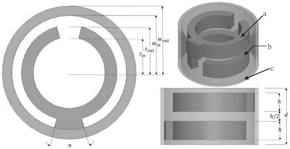
[0027] figure 1 It is a structural schematic diagram of the L-band metamaterial slow-wave structure disclosed in the prior art 1 in the background introduction. The structure is composed of a metamaterial unit a, a metamaterial unit b, and a circular waveguide c. The metamaterial unit 1 is a circular ring with a fan-shaped opening and a fan-shaped protrusion. The fan-shaped opening and the fan-shaped protrusion are respectively located on both sides of the ring, and the opening angles are both α. The inner radius of the circle is r in , the outer radius is r out , the thickness is h, and the inner radius of the circular waveguide is W in , the metama...


PUM

PropertyMeasurementUnit
sizeaaaaaaaaaa

Abstract

The invention relates to a meta-material-based L waveband slow wave structure. The meta-material-based L waveband slow wave structure utilizes two mutually orthogonally arranged meta-material resonantunits to form a single periodic slow wave structure, and can overcome the problem that electric fields are not distributed uniformly in an electron beam region because of asymmetry of the meta-material slow wave structure, so that the meta-material-based novel L waveband slow wave structure can operate below the cut-off frequency of a hollow metal waveguide with the same size and has an advantages of miniaturization.

Description

technical field [0001] The invention relates to microwave source devices in the technical field of high-power microwaves, in particular to an L-band slow-wave structure based on metamaterials. Background technique [0002] High-power microwave usually refers to electromagnetic waves with a peak power greater than 100MW and a frequency between 1 and 300GHz. It has been widely used in many national defense and industrial fields such as directed energy weapons, radar satellites, electronic high-energy radio frequency accelerators, remote sensing and radiation measurement. [0003] The high-power microwave source is the core component for generating high-power microwave radiation. The relativistic return wave oscillator uses the interaction between the high-current electron beam and the electromagnetic wave in the slow-wave structure to generate self-excited oscillation and amplify it to form coherent electromagnetic radiation. It has high power, The characteristics of high effi...

Claims


Application Information

Patent Timeline
Patent Type & Authority Patents(China)
IPC IPC(8): H01P9/00
CPCH01P9/00
Inventor 贺军涛戴欧志雄令钧溥宋莉莉
Owner NAT UNIV OF DEFENSE TECH
Why Eureka
Try Eureka