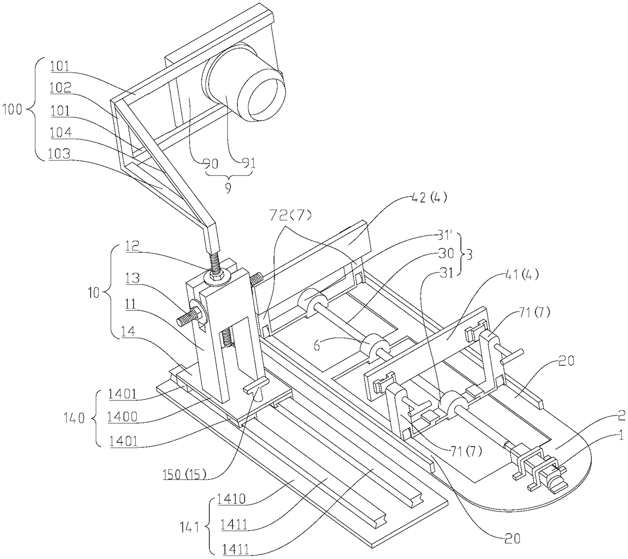
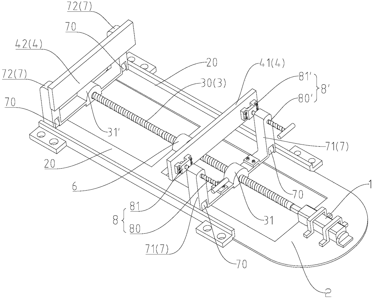
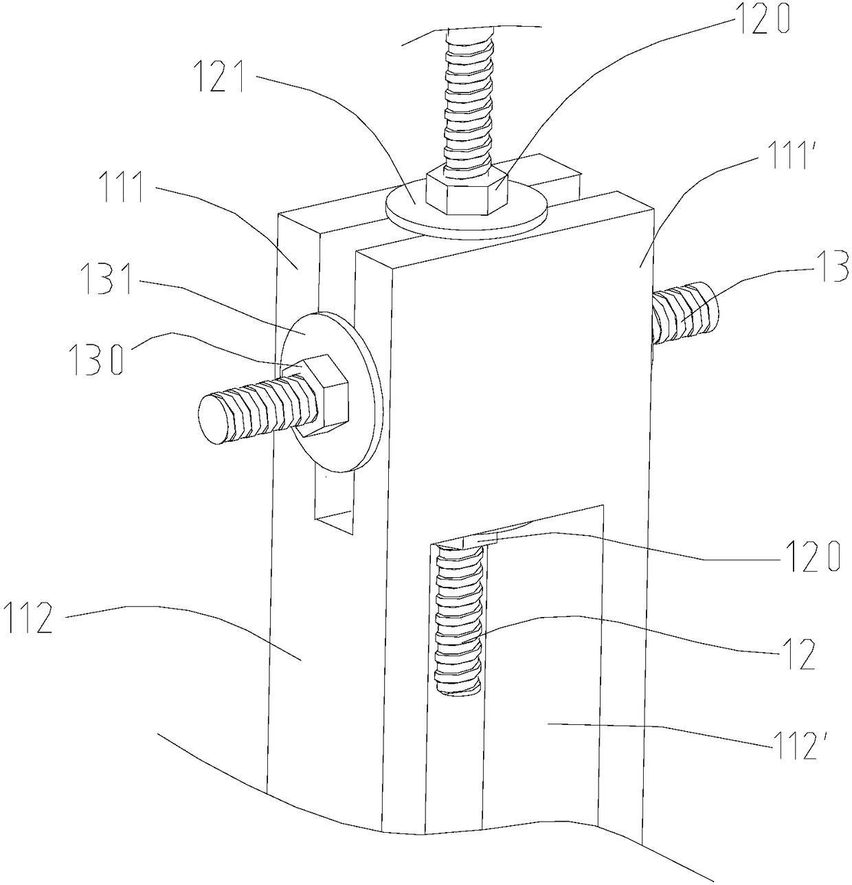
Glass kiln charging machine guiding device and glass kiln charging machine mounting structure
A glass kiln and guiding device technology, which is applied to the charging of the melting furnace, glass manufacturing equipment, manufacturing tools, etc., can solve the problems affecting the stability of the material mountain in the kiln, the influence of the process stability, and the limited melting capacity of the furnace.
- Summary
- Abstract
- Description
- Claims
- Application Information
AI Technical Summary
Problems solved by technology
Method used
Image

Examples
Embodiment Construction
[0065] Specific embodiments of the present disclosure will be described in detail below in conjunction with the accompanying drawings. It should be understood that the specific embodiments described here are only used to illustrate and explain the present disclosure, and are not intended to limit the present disclosure.
[0066] In this disclosure, unless stated to the contrary, the orientation words used such as "up, down, left, right, front, back" are generally relative to the normal use of the glass furnace charging machine installation structure , specifically, when the glass furnace charging machine installation structure is in normal use, the side of the charging machine installation structure facing the glass furnace is "front", and the side of the charging machine installation structure facing away from the glass furnace is "rear" ", when the installation structure of the feeder is facing the furnace wall of the glass furnace, the left side of the installation structur...
PUM
 Abstract
Description
Claims
Application Information
 - R&D Engineer
- R&D Manager
- IP Professional
- Industry Leading Data Capabilities
- Powerful AI technology
- Patent DNA Extraction
Browse by: Latest US Patents, China's latest patents, Technical Efficacy Thesaurus, Application Domain, Technology Topic.
© 2024 PatSnap. All rights reserved.Legal|Privacy policy|Modern Slavery Act Transparency Statement|Sitemap