A method for binding steel bars of coupling beams between prefabricated laminated slabs

A technology of steel bar binding and laminated panels, which is applied in the processing of building materials, construction, building construction, etc., can solve troublesome problems and achieve the effect of solving the difficulty of binding

Active Publication Date: 2020-04-28
JIANGSU HUAJIAN CONSTR
View PDF5 Cites 0 Cited by
  • Summary
  • Abstract
  • Description
  • Claims
  • Application Information

AI Technical Summary

Problems solved by technology

In the construction process of prefabricated buildings, the support system of laminated slabs is widely used. This system omits the formwork support in the horizontal direction, but the binding of the connecting beam reinforcement between the laminated slabs is much more troublesome than that of ordinary wood formwork, because the two sides of the laminated slabs The reinforcement inserted into the beam is reserved, and the reserved insertion reinforcement must all extend into the beam. Therefore, when binding the beam reinforcement, the stirrups and bottom reinforcement can only be bound and hoisted into the beam formwork, and then the gluten of the beam skeleton is bound.

Method used


Image

  • A method for binding steel bars of coupling beams between prefabricated laminated slabs
  • A method for binding steel bars of coupling beams between prefabricated laminated slabs
  • A method for binding steel bars of coupling beams between prefabricated laminated slabs

Examples


Embodiment Construction

[0014] The specific embodiment of the present invention is described below in conjunction with accompanying drawing:

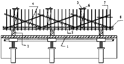
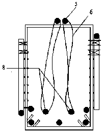
[0015] Such as figure 1 as shown, figure 1 It includes temporary binding operation platform 1, beam bottom reinforcement 2, frame 3, temporary fixing tool reinforcement 4, upper portable short reinforcement 5, binding wire 6, stirrup reinforcement 7, and beam upper longitudinal reinforcement 8. Beam bottom bars 2 and stirrups 7 are fastened, and squares 3 are 50*100 with a spacing of 800.

[0016] The construction process of the method for binding steel bars between the prefabricated laminated slabs of the present invention is specifically:

[0017] Firstly, a temporary binding operation platform 1 is set up on the side of the laminated slab across the beam, such as figure 2 shown.

[0018] Then on the horizontal formwork of the beam slab, the reinforcement beam binding frame body is supported on site.

[0019] Then bind the beam bottom reinforcement 2, ...


PUM


Abstract

The invention discloses a binding method for connecting beam steel bars between fabricated laminated slabs and belongs to the technical field of heat preservation of buildings. The binding method comprises the steps that firstly, a temporary binding operation platform is erected on the side of a laminated slab span beam; next, a steel bar beam binding frame is erected on site on a beam-slab horizontal formwork; and then, a beam bottom bar, stirrups and beam side waist bars are bound on the steel bar beam binding frame firstly, by considering the mutually laminated and pressed sequence of longitudinal and transverse beams and anchoring of the beam bars arranged in a wall and a column, temporary fixing tool bars are adopted on the outer side of a beam skeleton, and the temporary fixing toolbars are dismantled after the laminated slabs are arranged in place and beam surface bars are arranged in place. According to the binding method for the connecting beam steel bars between the fabricated laminated slabs, the problem that the connecting beam steel bars between the fabricated laminated slabs are difficult to bind is solved, and construction can be directed.

Description

technical field [0001] The invention specifically relates to a method for binding steel bars of connecting beams between assembled laminated panels, and belongs to the technical field of building construction methods. Background technique [0002] With the acceleration of the construction industrialization process, prefabricated buildings have sprung up like mushrooms after rain. In the construction process of prefabricated buildings, the support system of laminated slabs is widely used. This system omits the formwork support in the horizontal direction, but the binding of the connecting beam reinforcement between the laminated slabs is much more troublesome than that of ordinary wood formwork, because the two sides of the laminated slabs The reinforcement inserted into the beam is reserved, and the reserved insertion reinforcement must all extend into the beam. Therefore, when binding the beam reinforcement, the stirrups and bottom reinforcement can only be bound and hoiste...

Claims


Application Information

Patent Timeline
Patent Type & Authority Patents(China)
IPC IPC(8): E04G21/12
CPCE04G21/12E04G21/123
Inventor 邓凯缪昌华吴碧桥周起太刘成
Owner JIANGSU HUAJIAN CONSTR
Why Eureka
Try Eureka