Eureka AIR delivers breakthrough ideas for toughest innovation challenges, trusted by R&D personnel around the world.

Needle Card Fixing Ring Rotary Lifting Mechanism

A technology of rotating lifting and fixing rings, which is applied in the direction of instruments, measuring devices, and measuring electronics, can solve the problems of low efficiency of needle card replacement, insufficient compact structure, and small space occupation, and achieves simple and practical structure, small space occupation, and favorable The effect of making and installing

Active Publication Date: 2020-09-29
HANGZHOU CHANGCHUAN TECH CO LTD
View PDF8 Cites 0 Cited by
  • Summary
  • Abstract
  • Description
  • Claims
  • Application Information

AI Technical Summary

Problems solved by technology

[0003] The purpose of the present invention is to overcome the existing elevating device for realizing the lifting and lowering of the needle card fixing ring and the rotating device for realizing the rotation of the needle card fixing ring respectively. The structure is not compact enough to take up a lot of space and the efficiency of needle card replacement is low. To provide a needle card fixing ring rotary lifting mechanism with a compact structure that takes up less space and has a higher efficiency of needle card replacement

Method used


Image

  • Needle Card Fixing Ring Rotary Lifting Mechanism
  • Needle Card Fixing Ring Rotary Lifting Mechanism
  • Needle Card Fixing Ring Rotary Lifting Mechanism

Examples


Embodiment Construction

[0016] The present invention will be further described below in conjunction with the accompanying drawings.

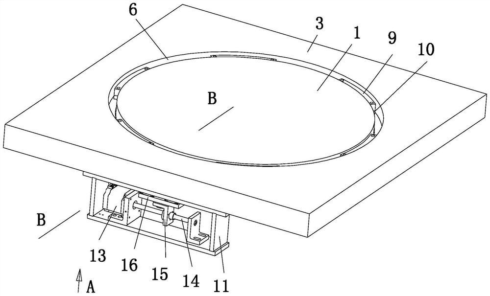
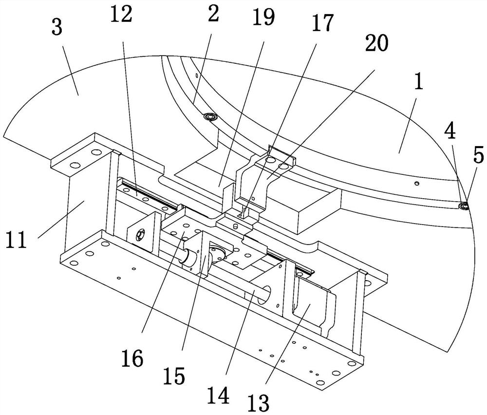
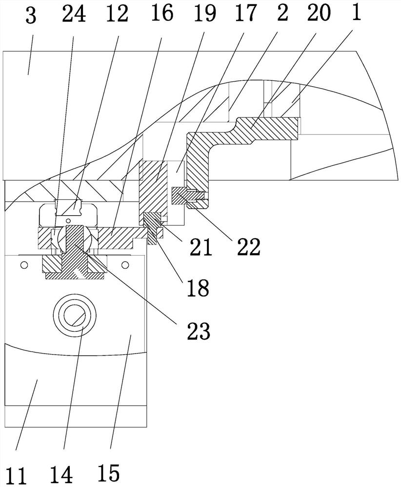
[0017] as attached figure 1 , attached figure 2 , attached image 3 , attached Figure 4 Shown: a needle card fixing ring rotary lifting mechanism, including: a rotary lifting plate 1, a base 3 provided with a through hole 2 outside the rotating lifting plate 1, and six holes that are in contact with the sides of the through hole 2 Limiting wheel 4 and the radial positioner 5 screwed to the lower end of the rotary lifting disc 1, the wedge-shaped rotary lifting mechanism arranged between the base 3 and the outer circumference of the rotary lifting disc 1, the rotary lifting drive device; the radial positioner 5 are evenly distributed along the circumference of the rotating lifting disc 1.

[0018] The wedge-shaped rotary lifting mechanism includes: an annular groove 6 arranged at the upper end of the through hole 2 and coaxial with the through hole 2, six wedge-sh...


PUM


Abstract

The invention provides a rotating and lifting mechanism of a pin clamp fixing ring. The rotating and lifting mechanism comprises a rotating and lifting plate, a base, a plurality of limiting wheels, aplurality of radial locators, an inclined-wedge-shaped rotating and lifting mechanism and a rotating-lifting driving device. The base with a through hole sleeves the rotating and lifting plate. The limiting wheels contact with the periphery of the through hole. The radial locaters are connected with the lower end of the rotating and lifting plate. The inclined-wedge-shaped rotating and lifting mechanism is arranged between the base and the outer periphery of the rotating and lifting plate. The radial locaters are distributed along the circumference of the rotating and lifting plate. The rotating and lifting mechanism has the advantages that the rotating and lifting plate is driven to rotate and rise through the rotating-lifting driving device, occupied space of the lifting structure is small, the rotating and lifting plate rotates and rises synchronously, and pin clamp replacement efficiency is high; through the limiting wheels contacting with the periphery of the through hole and theradial locaters connected with the lower end of the rotating and lifting plate, centring accuracy during rotating of the rotating and lifting plate is high, and axial lifting of the rotating and lifting plate is smooth.

Description

technical field [0001] The invention relates to the field of integrated circuit testing, in particular to a rotating and lifting mechanism for a fixed ring of a pin card. Background technique [0002] The rapid development of the integrated circuit industry has put forward higher requirements for the functions of wafer testing equipment; testing wafers through wafer testing equipment with automatic pick-and-place replacement of pin cards installed on the pin card fixing ring can improve test efficiency ; When replacing the needle card, it is necessary to lift the needle card fixing ring through the lifting device through the lifting platform, and rotate the needle card fixing ring through the rotating device; the traditional lifting device for realizing the lifting of the needle card fixing ring and the rotating device for realizing the rotation of the needle card fixing ring Set up separately, the lifting platform lifts the needle card fixing ring and the needle card fixing...

Claims


Application Information

Patent Timeline
Patent Type & Authority Patents(China)
IPC IPC(8): G01R1/067
CPCG01R1/06711
Inventor 舒贻胜陈思乡郭剑飞姚建强徐健伟虞思铭
Owner HANGZHOU CHANGCHUAN TECH CO LTD
Why Eureka
Eureka Blog
Learn More