Paper cropping device

A cutting and paper technology, applied in the cutting field, can solve the problems of affecting paper winding, uneven surface of transfer roller, production loss and so on

Inactive Publication Date: 2018-10-12
河南金宏印业有限公司
View PDF3 Cites 1 Cited by
  • Summary
  • Abstract
  • Description
  • Claims
  • Application Information

AI Technical Summary

Problems solved by technology

[0003] In the prior art, the paper cutting device does not have the setting of blowing the corner waste outward to fall on the outside of the cutting roller. During production, sometimes there is a gap on the side of the paper, causing the corner waste to be incoherent, and the corner waste behind the gap. Falling on the transfer roller, under normal circumstances, the transfer roller is flat, because there are corner waste falling on the transfer roller, resulting in uneven surface of the transfer roller, affecting the normal winding of the cut paper, and even causing production loss

Method used


Image

  • Paper cropping device

Examples


Embodiment Construction

[0015] The present invention will be further described below in conjunction with the accompanying drawings

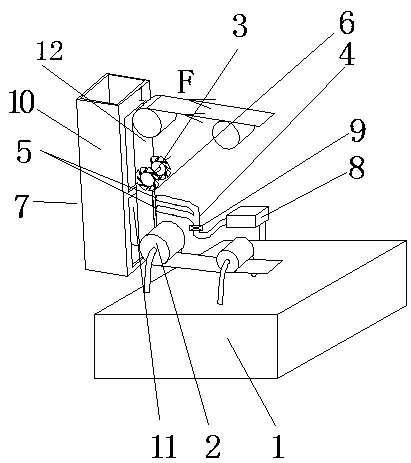
[0016] like figure 1 As shown, the paper cutting device includes a frame 1, with a transfer roller 2 and a cutting roller 3 on the frame, and the transfer roller is installed under the cutting roller, which is characterized in that: it is installed on the frame on the side of the cutting roller A blowing duct 4, the blowing duct has an outlet 5, the outlet faces the corner waste 6 produced in the cutting part and faces the outer side 7, and the blowing duct is connected to the air supply device 8.

[0017] When the present invention is used, the outlet of the blowing device blows air against the cutting part of the paper 12, so that the blowing outlet will blow out the scraps that fall off, so that they will not be involved in the conveying roller or fall into the printing device. , to ensure the normal use of the printing paper cutting device, the direction of the arr...


PUM


Abstract

The invention relates to the field of cropping technologies, and discloses a paper cropping device. The paper cropping device comprises a rack, a transferring roller and a cropping roller are arrangedon the rack, the transferring roller is installed below the cropping roller, the paper cropping device is characterized in that an air blowing pipe is installed on the position, on the side face of the cropping roller, of the rack, an outlet is formed in the air blowing pipe, faces the position, where leftover waste materials are generated, of the cropping part and faces the outer side, an air supply device is connected to the air blowing pipe, an adjusting valve is installed in the middle of the air blowing pipe, a containing box installed on the rack is further included and is provided withan opening, and the opening faces the outlet of the pipe. The paper cropping device has the advantages that the leftover waste materials can be prevented from falling to the transferring roller, andpaper obtained after cropping can be normally wound.

Description

technical field [0001] The invention relates to the technical field of cutting, in particular to a paper cutting device. Background technique [0002] The paper cutting device has a frame with a transfer roller and a cutting roller on the frame, the transfer roller is installed under the cutting roller, the paper runs on the transfer roller, and the paper is cut on the cutting roller. The cut corner waste falls on the outside of the cutter roll. [0003] In the prior art, the paper cutting device does not blow the corner waste to the outside of the cutting roller. In production, sometimes there are gaps on the side of the paper, resulting in inconsistency of the corner waste, and the corner waste behind the gap is It falls on the transfer roller. Under normal circumstances, the transfer roller is flat. Due to the corner waste falling on the transfer roller, the surface of the transfer roller is uneven, which affects the normal winding of the cut paper and even causes produc...

Claims


Application Information

Patent Timeline
Patent Type & Authority Applications(China)
IPC IPC(8): B26D7/18
CPCB26D7/1854
Inventor 曾龙恩孙萌萌金丽王会泳王瑞焱
Owner 河南金宏印业有限公司
Why Eureka
Try Eureka