
Intelligent accurate rotary-cut equipment
A precise and equipment technology, applied in the manufacture of veneer chips, wood processing appliances, manufacturing tools, etc., can solve the problems of increasing the economic cost of raw materials, large volume, and poor quality of wood chips.
- Summary
- Abstract
- Description
- Claims
- Application Information
AI Technical Summary
Problems solved by technology
Method used
Image

Examples
Embodiment Construction
[0048] In order to further explain the technical solutions of the present invention, specific examples are given below to illustrate in detail.
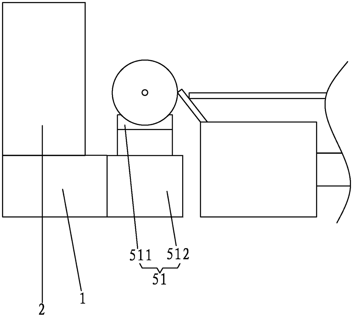
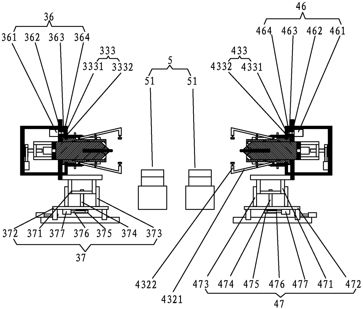
[0049] A kind of intelligent precision rotary cutting equipment of the present invention, such as Figure 1 to Figure 9 As shown, it includes a frame 1, a rotary cutting mechanism 2 and a clamping shaft arranged on the frame 1; the clamping shaft includes a first clamping part 3 at one end of the log, and a second clamping part 4 at the other end of the log ; Both the first clamping part 3 and the second clamping part 4 have a proximal end facing the direction of the log and a distal end facing the opposite direction; also include an initial support column 5 arranged under the log;
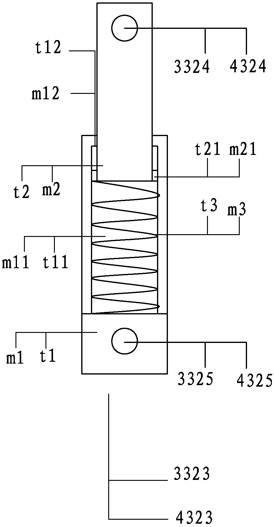
[0050] The first clamping part 3 includes a first main base plate 31 perpendicular to the log, a first positioning shaft mechanism passing through the first main base plate 31, and a first positioning sleeve mechanism sleeved outside the first positionin...
PUM
 Abstract
Description
Claims
Application Information