Seismic wave joint imaging method and system

An imaging method and imaging system technology, applied in the field of oil and gas geophysics, can solve the problems of high cost of velocity modeling, difficult to obtain accurately, and low calculation efficiency

Active Publication Date: 2018-10-23
CHINA PETROLEUM & CHEM CORP +1
View PDF9 Cites 0 Cited by
  • Summary
  • Abstract
  • Description
  • Claims
  • Application Information

AI Technical Summary

Problems solved by technology

However, these studies are mostly carried out in the pre-stack migration in the depth domain, and the velocity modeling in the necessary steps in the depth domain is very expensive, the calculation efficiency is low, and it is difficult to obtain it accurately (Wang Huazhong et al., 2012)

Method used


Image

  • Seismic wave joint imaging method and system
  • Seismic wave joint imaging method and system
  • Seismic wave joint imaging method and system

Examples


Embodiment Construction

[0028] The present invention will be described in more detail below with reference to the accompanying drawings. Although preferred embodiments of the invention are shown in the drawings, it should be understood that the invention may be embodied in various forms and should not be limited to the embodiments set forth herein. Rather, these embodiments are provided so that this disclosure will be thorough and complete, and will fully convey the scope of the invention to those skilled in the art.

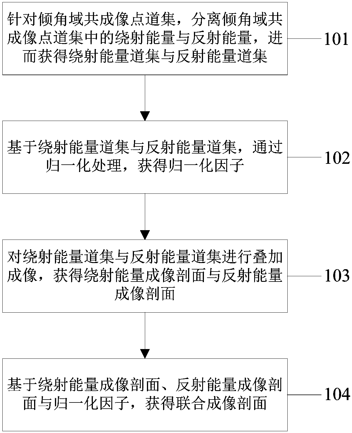
[0029] figure 1 A flowchart showing the steps of the seismic wave joint imaging method according to the present invention.

[0030] In this embodiment, the seismic wave joint imaging method according to the present invention may include: step 101, for the common imaging point gather in the dip domain, separate the diffraction energy and reflected energy in the common imaging point gather in the dip domain, and then obtain the diffraction energy gathers and reflected energy gathers; s...


PUM


Abstract

The invention discloses a seismic wave joint imaging method and system. The seismic wave joint imaging method can comprise the steps of for an inclination angle domain common imaging point gather, separating diffraction energy and reflection energy in the inclination angle domain common imaging point gather, and thus obtaining a diffraction energy gather and a reflection energy gather; obtaining anormalization factor through normalization processing based on the diffraction energy gather and the reflection energy gather; performing stack imaging on the diffraction energy gather and the reflection energy gather to obtain a diffraction energy imaging profile and a reflection energy imaging profile; and obtaining a joint imaging profile based on the diffraction energy imaging profile, the reflection energy imaging profile and the normalization factor. The seismic wave joint imaging method can simultaneously represent a reflector and a diffractor more clearly and more accurately through joint imaging of reflected waves and diffracted waves.

Description

technical field [0001] The present invention relates to the technical field of oil and gas geophysics, and more specifically, to a seismic wave joint imaging method and system. Background technique [0002] The energy result of the seismic signal can be represented in the reflected energy or the diffracted energy. In the reflected seismic data, the reflected wave is the reflection of the interface shape of the underground layered strata, which is mainly characterized by continuity, while the diffracted wave It reflects the important information of irregular anomalies in the underground medium, mainly manifested as discontinuity features, such as pinch-out of sand bodies, unconformities, large-scale faults, and small-scale geological anomalies such as holes, caves, and fractures (Khaidukov, 2003 ). For the identification and description of these irregular geological anomalies, especially for the understanding of complex heterogeneous carbonate karst fracture-cavity reservoir...

Claims


Application Information

Patent Timeline
Patent Type & Authority Applications(China)
IPC IPC(8): G01V1/34
CPCG01V1/345
Inventor 刘志远刘俊州刘喜武刘宇巍张远银霍志周刘炯
Owner CHINA PETROLEUM & CHEM CORP
Why Eureka
Try Eureka