A method for evaluating and predicting the service life wear of shield tunneling tools

A shield tool and tool wear technology, which is applied in the direction of instruments, design optimization/simulation, calculation, etc., can solve the problems of small application range, low work efficiency, no measurement function, etc., and achieve simple, convenient and economical operation, convenient use, and application wide range of effects

Active Publication Date: 2020-06-26
HUAZHONG UNIV OF SCI & TECH +1
View PDF2 Cites 0 Cited by
  • Summary
  • Abstract
  • Description
  • Claims
  • Application Information

AI Technical Summary

Problems solved by technology

Tool wear is generally measured visually or with a ruler, which is inefficient, inaccurate, and only approximate maximum wear data can be obtained; odor detection can report tool wear information sensitively, but this method is only suitable for In the TBM, it is invalid in the shield machine; in the oil pressure wear detection, due to the limited oil circuit, limited by the number of oil circuits, it can only be installed on a small number of tools, and it is impossible to know whether other tools are worn, and it is impossible Obtain the specific wear amount of the tool; there are also hydraulic or electronic sensor systems installed in the cutter head, or use optical fiber short circuit or ultrasonic to judge the degree of tool wear. Once the wear reaches a certain level, it will automatically alarm, but this method There is only an early warning function and no measurement function; Herrenknecht once proposed a scraper with a wear detector, but the sensing device can only be installed on a small number of knives, and the application range is small; there are also acoustic emission devices used to detect the wear status of the knives method, the acoustic emission signal is used as the input of the artificial neural network, and the neural network automatically judges whether the tool has worn out, but this method does not solve the problem of the size measurement of the worn part

Method used


Image

  • A method for evaluating and predicting the service life wear of shield tunneling tools

Examples


Embodiment Construction

[0021] In order to make the object, technical solution and advantages of the present invention clearer, the present invention will be further described in detail below in conjunction with the accompanying drawings and embodiments. It should be understood that the specific embodiments described here are only used to explain the present invention, not to limit the present invention. In addition, the technical features involved in the various embodiments of the present invention described below can be combined with each other as long as they do not constitute a conflict with each other.

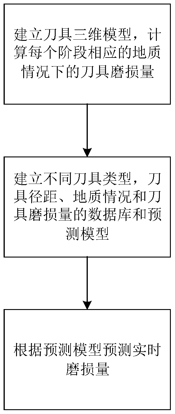
[0022] The invention provides a method for evaluating and predicting wear of a shield tool during service, which specifically includes the following steps:

[0023] (a) According to the actual tunneling conditions of the shield machine, the service period of the shield machine tool is divided into multiple stages, and a three-dimensional model of the shield machine tool is established at the end...


PUM


Abstract

The invention belongs to the field of shield cutter abrasion detection, and discloses a visual evaluation and prediction method for shield cutter service period abrasion. The method comprises the following steps that: (a) dividing a shield cutter use process into a plurality of stages, recording the geological situation of each stage, establishing a three-dimensional model when each stage ends, and comparing cutter models of two adjacent stages to obtain a cutter abrasion loss; (b) selecting different types of cutters and the same type of cutters of different ranges, obtaining the corresponding cutter abrasion loss under different geological situations, and forming the database and the prediction model of cutter types, cutter ranges, geological situations and cutter abrasion losses; and (c) determining the cutter type, the cutter range and the to-be-tunneled geological environment of the shield cutter to be predicted, and inputting the cutter type, the cutter range and the to-be-tunneled geological environment into the prediction model to obtain the abrasion loss of each point of a cutter abrasion surface to realize the visual evaluation and prediction of the cutter abrasion. Through the method, under the corresponding geological situation of the cuter, the abrasion loss of each point of the cutter abrasion surface can be accurately calculated, short time is consumed, and an application range is wide.

Description

technical field [0001] The invention belongs to the field of shield tool wear detection, and more particularly relates to a method for evaluating and predicting wear of a shield tool during service. Background technique [0002] With the advancement of science and technology, the improvement of people's living standards, and the development of urban construction, urban land resources are becoming increasingly tense, and underground resources have become an indispensable development resource in the process of modern urban construction. Shield construction technology is an advanced tunnel construction technology developed with the needs of modern transportation, underground engineering, mining, water conservancy projects, and municipal construction; the shield machine relies on the cutter on the cutter head to cut the soil continuously. , during the tunneling process, the tool will inevitably be impacted and worn, but how to quickly and accurately judge the wear degree of the ...

Claims


Application Information

Patent Timeline
Patent Type & Authority Patents(China)
IPC IPC(8): G06F30/20G06T17/00
CPCG06F30/20G06T17/00
Inventor 陈健丁烈云魏林春周迎赵峻柯钊朱雁飞雷蕾王志华
Owner HUAZHONG UNIV OF SCI & TECH
Why Eureka
Try Eureka