Spring bolt controller

A controller and lock tongue technology, applied in building locks, buildings, building structures, etc., can solve problems such as difficulty in adapting to doors of different thicknesses and door seams of different widths, failures, etc.

Inactive Publication Date: 2018-11-02
李嘉斌
View PDF4 Cites 0 Cited by
  • Summary
  • Abstract
  • Description
  • Claims
  • Application Information

AI Technical Summary

Problems solved by technology

It is difficult for a light touch spring lock of one specification to adapt to doors of different thicknesses and door gaps of different widths
If the thickness of the door body or the width of the door gap is not suitable, the function of the light touch spring lock to prevent the bolt from colliding with the door frame will fail

Method used


Image

  • Spring bolt controller
  • Spring bolt controller
  • Spring bolt controller

Examples


Embodiment Construction

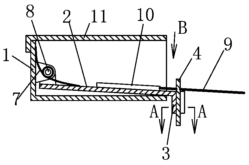
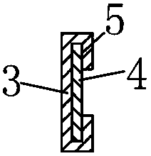
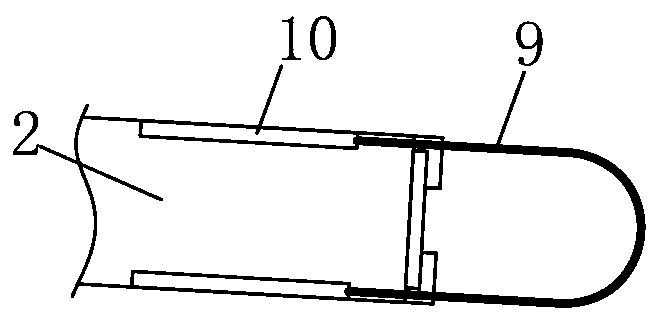
[0015] see figure 1 According to the present invention, a deadbolt controller includes a base 1 and a rotating plate 2 . The rotating plate 2 protrudes from the edge of the base 1 and bends toward the bottom of the base 1 to form a bent portion 3 . The bent portion 3 is connected with a baffle plate 4 . see figure 2 , the two edges of the bent portion 3 are bent to form the slot 5 for clamping the baffle 4 . Baffle 4 in Figure 4 The position in the direction shown by the arrow C is adjustable, that is, the position in the direction perpendicular to the telescopic direction of the dead bolt 6 is adjustable. A torsion spring 7 is connected between the rotating plate 2 and the base 1 . The torsion spring 7 is sleeved on the rotating shaft 8 of the rotating plate 2 . see Figure 4 , the rotating plate 2 can drive the baffle plate 4 to move to the position where the locking bolt 6 protrudes under the action of the spring 7 .

[0016] see figure 1 , image 3 , is connect...


PUM


Abstract

A spring bolt controller comprises a base and a rotating plate rotationally connected with the base. The rotating plate extends out of the edge of the base and is bent towards the position below the base to form a bent part; the bent part is connected with a baffle; the position of the baffle is adjustable in the direction perpendicular to the extension direction of a spring bolt; a spring is connected between the rotating plate and the base; under action of spring force, the rotating plate can drive the baffle to move to the position where the baffle prevents outward extension of the spring bolt; a front rod is connected to the rotating plate, the rotating can be driven to rotate through the front rod, and the rotating plate can drive the baffle to leave the front end of the spring bolt under driving of the front rod; and the position of the front rod is adjustable in the direction parallel to the extension direction of the spring bolt. The spring bolt controller has the advantages ofbeing capable of adapting to doors bodies of different thicknesses and door slots of different thicknesses, and capable of achieving the effect of preventing the spring bolt of a spring lock from colliding with a door frame when a door is closed.

Description

technical field [0001] The invention relates to a device installed on a door body, in particular to a device for controlling the bolt of a snap lock on the door body. Background technique [0002] There is a type of light touch snap lock in the snap lock. This type of light touch snap lock features a controlled deadbolt that does not hit the door frame when closing the door. However, different door bodies have different thicknesses, and the door gap between the door edge and the door frame will also have different widths. It is difficult for a light-touch spring lock of one specification to adapt to door bodies of different thicknesses and door gaps of different widths. If the thickness of the door body or the width of the door gap is not suitable, the function of the light touch spring lock to prevent the deadbolt from colliding with the door frame will fail. Contents of the invention [0003] The object of the present invention is to provide a deadbolt controller, whi...

Claims


Application Information

Patent Timeline
Patent Type & Authority Applications(China)
IPC IPC(8): E05B63/20
CPCE05B63/20
Inventor 陈振越李嘉斌
Owner 李嘉斌
Why Eureka
Try Eureka