Control method of built-in permanent-magnet synchronous motor

A technology of permanent magnet synchronous motor and control method, which is applied in motor control, motor generator control, AC motor control, etc., and can solve the problems that motor efficiency and load capacity cannot be optimized, so as to reduce motor loss and improve operating efficiency Effect

Inactive Publication Date: 2018-11-02
NANJING UNIV OF SCI & TECH
View PDF0 Cites 10 Cited by
  • Summary
  • Abstract
  • Description
  • Claims
  • Application Information

AI Technical Summary

Problems solved by technology

But because the q-axis voltage is a given constant, the motor efficiency and load capacity cannot be optimized under different working conditions

Method used


Image

  • Control method of built-in permanent-magnet synchronous motor
  • Control method of built-in permanent-magnet synchronous motor
  • Control method of built-in permanent-magnet synchronous motor

Examples


Embodiment Construction

[0025] The present invention will be described in further detail below in conjunction with the accompanying drawings.

[0026] With reference to the drawings, the control method of a built-in permanent magnet synchronous motor of the present invention includes the following steps:

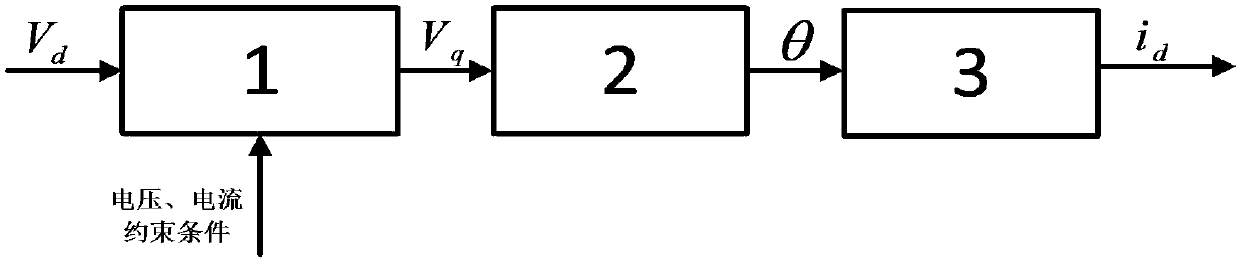
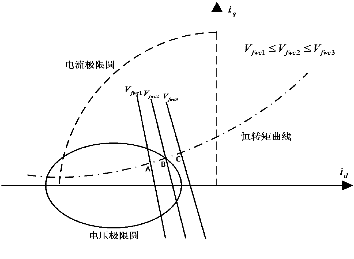
[0027] Step 1. Use the field weakening control method to construct the rotor closed-loop system, obtain the d-axis voltage response, and obtain the corresponding q-axis voltage V fwc And judge whether the current and voltage at the stable operating point meet the limit circle constraint, if not, select the appropriate V fwc ;

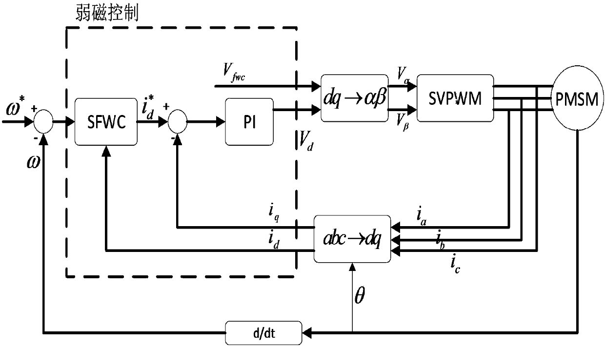
[0028] Construct a closed-loop field weakening control rotor system, estimate the rotor synchronous rotating coordinate d-axis current through coordinate transformation, and obtain the reference d-axis current through the field weakening regulator, which includes the field weakening component and the torque component; under a fixed q-axis voltage, The d-axis current is automaticall...


PUM


Abstract

The invention discloses a control method of a built-in permanent-magnet synchronous motor. The control method comprises the steps of 1) building a rotor closed-loop system by a weak flux control method, acquiring d-axis voltage response, solving a corresponding q-axis voltage, judging whether a current and a voltage of a stable running point conform to limit circle constraint or mot, and selectingan appropriate voltage according to a rule if the current and the voltage do not conform to the limit circle constraint; 2) calculating current reduction gradient and a constant-torque direction by the stable running point, and solving an angle by a vector product; and 3) judging a direction which makes the current reduced according to the angle, and changing the voltage so that the running pointmoves towards a direction of current reduction. By the control method, relatively large power of a weal flux high-speed region of the motor is considered, the system loss is increased due to increasing of a de-magnetism current, and the situations of different loads and rotational speeds are adapted by constantly correcting the q-axis voltage; and on the basis of analyzing single-current weak flux control, the quadrature-axis voltage is optimized and corrected on line according to a projection relation of the constant-torque direction of the running point of the motor on the current reductiongradient, so that the working current of the motor reaches minimum.

Description

Technical field [0001] The invention relates to the field of motors, in particular to a control method of a built-in permanent magnet synchronous motor. Background technique [0002] Built-in permanent magnet synchronous motors are widely used in high-performance speed regulation systems such as electric vehicle drive systems due to their outstanding advantages such as high efficiency, high power density, and easy field weakening. Electric vehicles and other systems require a wide speed range ω to meet the requirements of high-speed driving, so the research on the field weakening control in the high-speed area of ​​IPMSM is very important. In the traditional field weakening strategy, there are two current regulators in the system to adjust the dq-axis current separately. The saturation of the regulator and the mutual coupling of the dq-axis current in the high-speed stage will deteriorate the system's regulation performance on the motor speed, current and torque. , And even lead...

Claims


Application Information

Patent Timeline
Patent Type & Authority Applications(China)
IPC IPC(8): H02P21/00H02P21/22H02P25/022
CPCH02P21/00H02P2207/05
Inventor 徐波朱莲莉夏义云珂王邦兴
Owner NANJING UNIV OF SCI & TECH
Why Eureka
Try Eureka