An intelligent network security door
What is Al technical title?
Al technical title is built by PatSnap Al team. It summarizes the technical point description of the patent document.
A technology of intelligent networking and anti-theft doors, which is applied in the field of anti-theft doors, can solve the problems of inconvenient remote monitoring and poor security, and achieve the effect of reducing the occupied area and high safety in use
Inactive Publication Date: 2019-11-12
四川嘉威门业有限公司
View PDF10 Cites 0 Cited by
Summary
Abstract
Description
Claims
Application Information
AI Technical Summary
This helps you quickly interpret patents by identifying the three key elements:
Problems solved by technology
Method used
Benefits of technology
Problems solved by technology
[0003] The purpose of the present invention is to provide an intelligent networked anti-theft door, which solves the problems of poor safety and inconvenient remote monitoring of existing anti-theft door locks
Method used
Image
Click on the blue label to locate the original text in one second.
Reading with bidirectional positioning of images and text.
Examples
Embodiment Construction
[0026] The embodiments of the present invention will be described in detail below with reference to the accompanying drawings, but the present invention can be implemented in many different ways defined and covered by the claims.
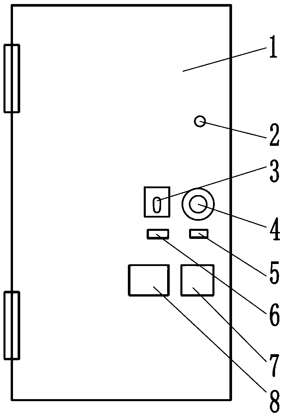
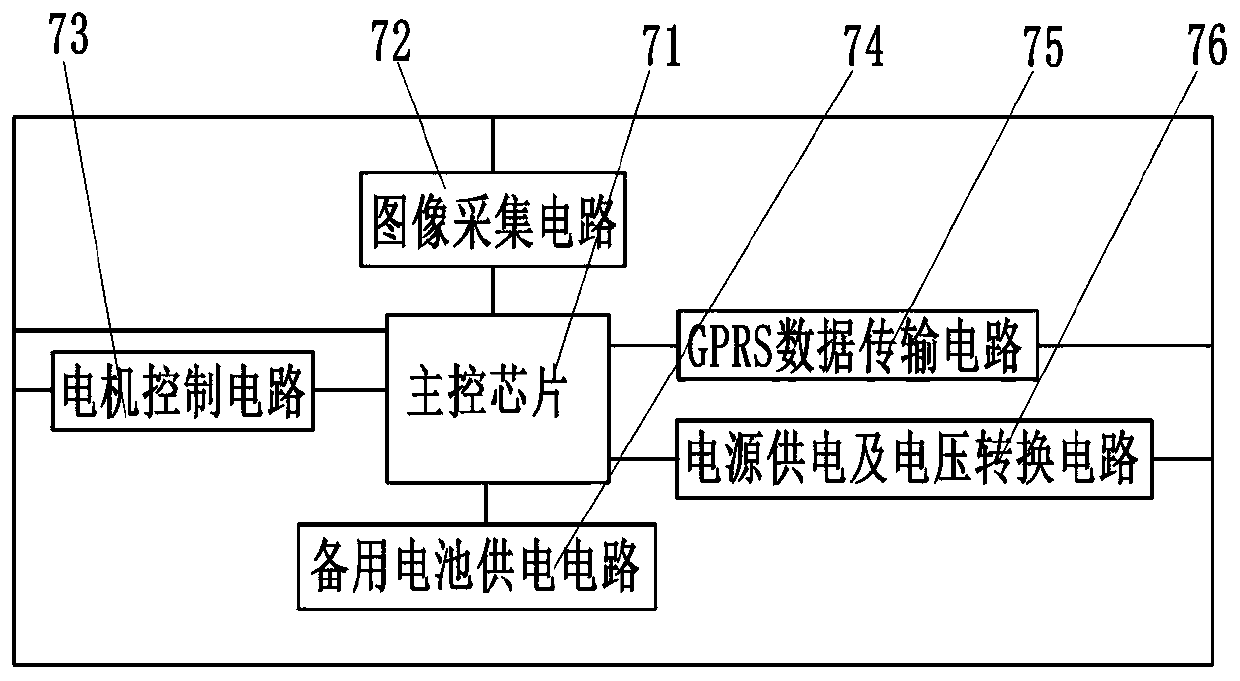
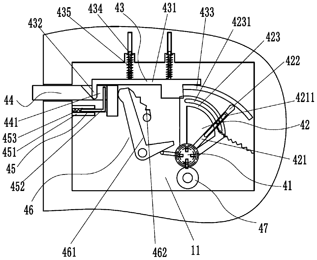
[0027] Refer below Figure 1 to Figure 5 To further explain this application, such as figure 1 , image 3 and Figure 4 A kind of intelligent networking anti-theft door shown includes a door body 1, a lock body 4 installed in the installation cavity 11 of the door body 1, a camera 2 installed on the door body 1, a fingerprint recognition device 3, a microwave Sensor 5, pyroelectric sensor 6, circuit board 7, backup battery 8, described microwave sensor 5, pyroelectric sensor 6 are used to detect whether there are people active in front of the door, if any, then signal is transmitted to circuit board 7, The circuit board 7 controls the camera 2 to open for image collection and upload, and the fingerprint recognition device 3 starts the fingerprint...
PUM
Abstract
The invention provides an intelligent networking security door which comprises a door body, a camera, a fingerprint identification device, a lock body, a microwave sensor and a pyroelectric sensor. The camera, the fingerprint identification device, the lock body, the microwave sensor and the pyroelectric sensor are installed on the door body, the lock body comprises a lock cylinder, a driving assembly, a self-locking mechanism, a spring bolt, a reset mechanism, a lock reset mechanism and a driving gear, the driving gear is engaged with a driven gear located on the lock cylinder and is coaxially connected with a handle on the inner side, an ejection rod of the driving assembly is connected with the lock cylinder, the ejection rod can enable the self-locking mechanism to be separated from the spring bolt, and the released spring bolt inwards contracts under the effect of the rest mechanism; and when the spring bolt extends outwards, a driving support of the driving assembly rotates reversely to enable the driving support to act on the lock reset mechanism to enable the lock reset mechanism to abut against the back end face of the spring bolt, meanwhile, the driving support acts on the lock cylinder to prevent the lock cylinder from rotating, after the driving support rotates forwards, the lock reset mechanism resets, and the lock cylinder can be rotated to achieve unlocking. Whenthe intelligent networking security door is locked, the lock cylinder cannot be rotated, the lock reset mechanism abuts against the back end of the spring bolt, and therefore safety is high.
Description
technical field [0001] The invention relates to an anti-theft door, in particular to an intelligent networking anti-theft door. Background technique [0002] In recent years, with the continuous news of stolen houses and companies, people pay more and more attention to safety. For the door of the room where important items are stored, people prefer anti-theft doors, although the existing anti-theft doors are all Using metal materials, if only mechanical locks are used, there is still a risk of being easily pried open. Therefore, intelligent anti-theft doors have become a trend. The existing intelligent anti-theft door locks include a deadbolt and a driving mechanism, and the deadbolt and the driving mechanism are directly connected. Drive connection, when the correct input information is recognized, the circuit board will control the drive mechanism to work so that the deadbolt shrinks to open the door. When the wrong input information is recognized, the door lock will not o...
Claims
Application Information
Patent Timeline
Application Date:The date an application was filed.
Publication Date:The date a patent or application was officially published.
First Publication Date:The earliest publication date of a patent with the same application number.
Issue Date:Publication date of the patent grant document.
PCT Entry Date:The Entry date of PCT National Phase.
Estimated Expiry Date:The statutory expiry date of a patent right according to the Patent Law, and it is the longest term of protection that the patent right can achieve without the termination of the patent right due to other reasons(Term extension factor has been taken into account ).
Invalid Date:Actual expiry date is based on effective date or publication date of legal transaction data of invalid patent.