Fan having dust suction function

A fan and functional technology, which is applied in the field of fans with dust collection function, can solve the problems of affecting dust reabsorption, suction end suction reduction, etc.

Inactive Publication Date: 2018-11-09
安徽悦达环保科技有限公司
View PDF8 Cites 3 Cited by
  • Summary
  • Abstract
  • Description
  • Claims
  • Application Information

AI Technical Summary

Problems solved by technology

[0003] At present, the existing fan generally intercepts dust by setting a dust-proof net behind the fan. When the vacuuming time is long, the dust will often block the dust-proof net, which will affect the re-absorption of dust, and the suction at the suction end will also be greatly reduced.

Method used


Image

  • Fan having dust suction function
  • Fan having dust suction function
  • Fan having dust suction function

Examples


Embodiment Construction

[0021] Below in conjunction with accompanying drawing and embodiment of description, specific embodiment of the present invention is described in further detail:

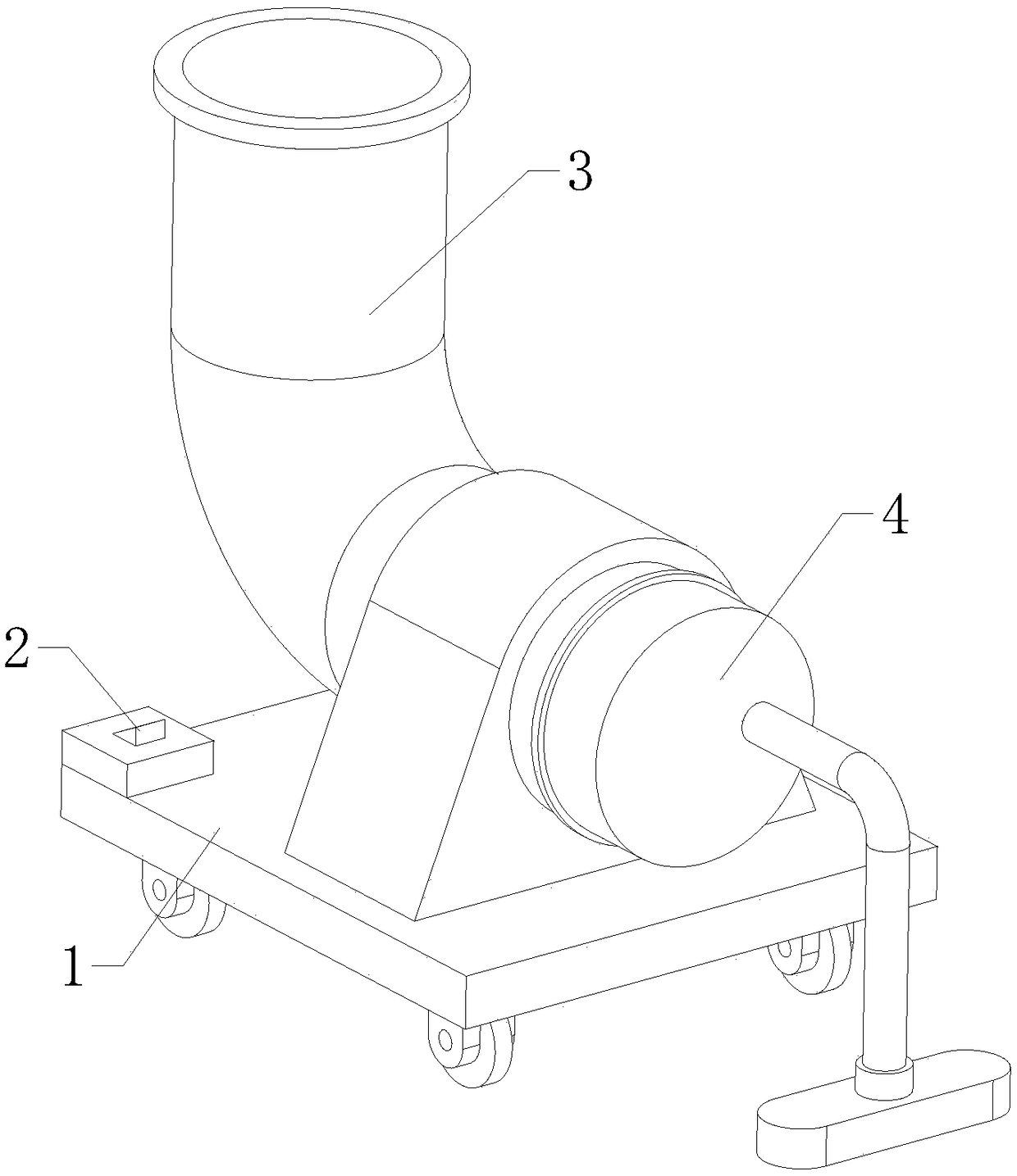
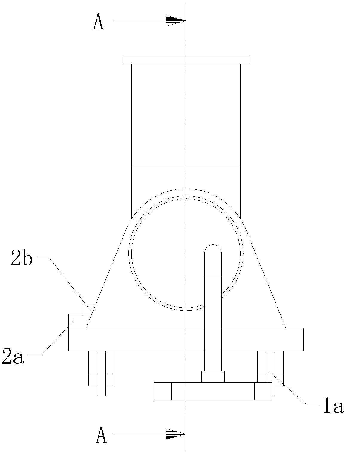
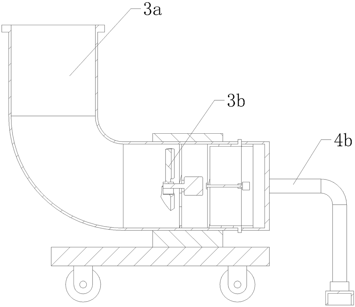
[0022] refer to Figure 1 to Figure 6 A blower fan with a dust suction function shown includes a chassis 1, a control assembly 2 arranged on the chassis 1, a blower assembly 3 and a dust suction assembly 4 fixedly arranged on the chassis 1, and the blower assembly 3 includes The blast pipe 3a and the exhaust fan 3b, the blast pipe 3a is fixedly arranged on the top of the chassis 1, the exhaust fan 3b is fixed inside the blast pipe 3a, and the dust suction assembly 4 includes a storage part 4a and a dust suction part 4b, the storage part 4a is detachably arranged inside the blast pipe 3a, the dust suction part 4b is detachably arranged on the dust suction part 4b and communicated with the dust suction part 4b, the control assembly 2 is connected to the blower Both the wind component 3 and the dust suction component ...


PUM


Abstract

The invention relates to the field of fans, in particular to a fan having the dust suction function. The fan comprises a bottom disc, a control assembly, an air blowing assembly and a dust suction assembly, wherein the control assembly is arranged on the bottom disc, and the air blowing assembly is fixedly arranged on the bottom disc. The air blowing assembly comprises an air blowing pipe and an exhaust fan. The dust suction assembly comprises a storage component and a dust suction component. The storage component is detachably arranged inside the air blowing pipe. The dust suction component is detachably arranged on the air blowing pipe and communicates with the air blowing pipe. When the fan carries out the dust suction work, the control assembly controls the air blowing assembly to be opened; the exhaust fan exhausts air out of the air blowing pipe, and furthermore, reverse direction air suction can be conducted; the dust suction assembly is used for filtering out dust while conducting air suction; the dust suction component is used for sucking in air and the dust; and the storage component is used for incepting the dust in the air and stores the dust into the storage component,and furthermore, the dust removal effect is achieved.

Description

technical field [0001] The invention relates to the field of fans, in particular to a fan with dust suction function. Background technique [0002] The fan is mainly composed of the following six parts: motor, air filter, fan body, air chamber, base, and drip nozzle. The fan operates eccentrically by the offset rotor in the cylinder, and makes the volume change between the blades in the rotor slot suck in, compress and spit out air. During operation, the pressure difference of the fan is used to automatically send lubrication to the drip nozzle, and drip into the cylinder to reduce friction and noise, and at the same time keep the gas in the cylinder from flowing back. This type of fan is also called a sliding vane fan. [0003] At present, the existing fan generally intercepts dust by setting a dust-proof net behind the fan. When the vacuuming time is long, the dust will often block the dust-proof net, thereby affecting the re-absorption of dust, and the suction at the suc...

Claims


Application Information

Patent Timeline
Patent Type & Authority Applications(China)
IPC IPC(8): F04D25/08F04D29/00F04D29/52F04D29/70
CPCF04D25/08F04D29/002F04D29/522F04D29/703
Inventor 奚林奚小平
Owner 安徽悦达环保科技有限公司
Why Eureka
Try Eureka