Light convergence structure and backlight module

A light and light source technology, applied in light guides, optics, optical components, etc., can solve problems such as brightness reduction, achieve the effect of light convergence and ensure brightness

Inactive Publication Date: 2021-03-26
BOE TECH GRP CO LTD +1
View PDF4 Cites 0 Cited by
  • Summary
  • Abstract
  • Description
  • Claims
  • Application Information

AI Technical Summary

Problems solved by technology

[0003] In order to solve the above technical problems, the present invention provides a light converging structure and a backlight module to solve the problem of brightness reduction caused by converging light

Method used


Image

  • Light convergence structure and backlight module
  • Light convergence structure and backlight module
  • Light convergence structure and backlight module

Examples


Embodiment Construction

[0031] The structure and features of the present invention will be described in detail below in conjunction with the accompanying drawings, and the examples given are only used to explain the present invention, not to limit the protection scope of the present invention.

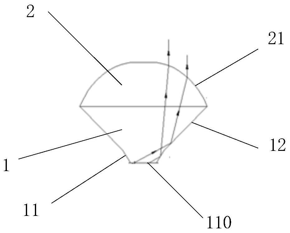
[0032] This embodiment provides a light converging structure for converging the light emitted from the light-emitting surface of the light guide plate, including a body disposed on the light-emitting surface of the light guide plate, and the body includes a plurality of light converging parts 4, each of which The ray converging part 4 includes:

[0033] The truncated circular structure 1 includes a first end surface 110 in contact with the light guide plate and a second end surface opposite to the first end surface 110, and the area of ​​the first end surface 110 is smaller than that of the second end surface area;

[0034] Plano-convex structure 2, described second end surface of described frustum of circul...


PUM


Abstract

A light convergence structure includes light convergence portions. Each light convergence portion includes a frustum structure and a plano-convex structure. The frustum structure includes a first end surface and an opposite second end surface. An area of the first end surface is less than an area of the second end surface. The plano-convex structure is on the second end surface of the frustum structure. The plano-convex structure includes a flat surface and an opposite convex spherical surface. The flat surface is in contact with the second end surface. An area of the flat surface is equal to the area of the second end surface. The first end surfaces of the light convergence portions are coplanar and together define a light incident surface of the light convergence structure.

Description

technical field [0001] The invention relates to the technical field of liquid crystal product production, in particular to a light converging structure and a backlight module. Background technique [0002] Smart display includes features such as anti-peeping, HDR (High-Dynamic Range, high-dynamic range imaging), low power consumption, and extreme module structure. It is one of the technological trends in the development of the display industry today. However, the technical bottleneck of directional optics in smart display technology lies in the collimation of light beams. Existing collimation solutions include thin-film digging, adding absorption gratings, etc. Although these solutions can achieve a certain near-collimation effect, the brightness is reduced by more than 30%. , the thickness of the module will also increase, which not only does not meet the design requirements of low power consumption, but also does not meet the development trend of extreme module structure. ...

Claims


Application Information

Patent Timeline
Patent Type & Authority Patents(China)
IPC IPC(8): G02F1/13357
CPCG02F1/133606G02F1/133607G02B6/0036G02B6/0053G02F1/133603G02B6/0063G02F1/133615
Inventor 汤海揭景斌高露秦建伟高亮韩波
Owner BOE TECH GRP CO LTD
Why Eureka
Try Eureka