
Lateral steering lamp

A technology for turning lights and lamp holders, which is applied in lighting and heating equipment, transportation and packaging, road vehicles, etc. It can solve the problems of affecting the appearance of the whole vehicle, poor sealing, and inconvenient installation methods, and achieve enhanced light distribution effects Effect

Inactive Publication Date: 2018-11-23
江苏江龙汽车系统有限公司
View PDF0 Cites 0 Cited by
  • Summary
  • Abstract
  • Description
  • Claims
  • Application Information

AI Technical Summary

Problems solved by technology

[0002] The function of the side turn signal installed on the car is: when the vehicle is turning, the light group that warns other vehicles is generally located on both sides of the vehicle body; the side turn signal installed on the car is mainly installed by injecting glue into the In the loading hole of the car, press the lamp into the loading hole, and connect the two with glue; but this installation method is very inconvenient, and the gap between the surface of the lamp and the loading hole is easy to appear after installation. Uniform, unattractive appearance; In addition, due to the high labor requirements for glue application, excessive glue spillage will affect the appearance of the vehicle, less adhesion and poor sealing
In the past, due to the high installation position of the rear position indicator lights with turn signals, the aesthetic requirements of the lights were not high, and the 3M glue was pasted on the car body, and the 3M would appear to be weakly bonded and fall off during long-term use.

Method used


Image

  • Lateral steering lamp
  • Lateral steering lamp
  • Lateral steering lamp

Examples


Embodiment Construction

[0020] The implementation of the present invention will be described in detail below with reference to the drawings and examples, so as to fully understand and implement the implementation process of how to use technical means to solve technical problems and achieve technical effects in the present invention.

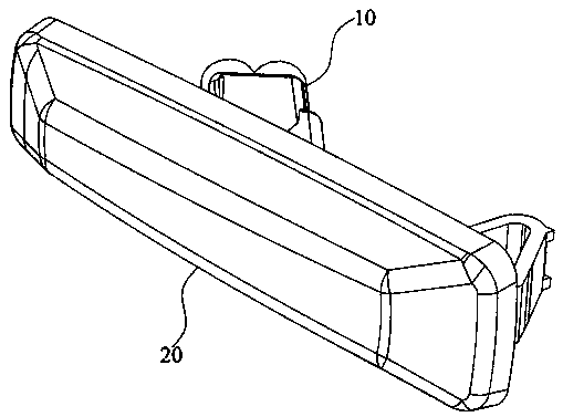
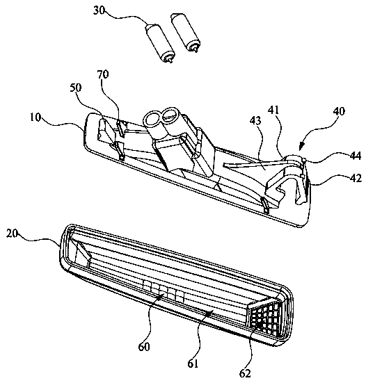
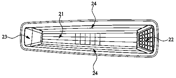
[0021] Please also refer to Figure 1 to Figure 3 , figure 1 It is a perspective view of the side turn signal of the embodiment of the present invention; figure 2 It is an explosion diagram of the side turn signal lamp of the embodiment of the present invention; image 3 It is a schematic diagram of the lampshade shell of the embodiment of the present invention. As shown in the figure, a side turn signal lamp includes a lamp holder housing 10, a lampshade housing 20 covering the lamp holder housing 10, and a wave plug bulb 30 inserted into the lamp holder housing 10; wherein, the lamp holder The two ends of the shell 10 have a first elastic buckle 40 and a second fi...


PUM


Abstract

The invention discloses a lateral steering lamp. The lateral steering lamp comprises a lamp seat shell, a lampshade shell and a bulb, wherein the lampshade shell covers the lamp seat shell; the bulb is arranged in the lamp seat shell in a penetrated manner; a first elastic buckle and a second fixed buckle are separately arranged at two ends of the lamp seat shell; the lampshade shell is in the shape of a boss, and is provided with a central light guiding surface, a front light guiding surface, a rear light guiding surface and lateral side guiding surfaces; the central light guiding surface faces the bulb; the front light guiding surface is adjacent to the central light guiding surface and faces the front end of an automobile; the rear light guiding surface is adjacent to the central lightguiding surface and faces the rear end of the automobile; and the lateral light guiding surfaces are connected to the front light guiding surface and the rear light guiding surface and are oppositelyarranged on the two sides of the central light guiding surface. The first elastic buckle of the lamp seat shell is matched with the second fixed buckle and is mounted and fixed to an automobile body,then the lampshade shell uniformly and effectively guides light, and the troubles that an existing lateral steering lamp is mounted to the automobile body infirmly and the light distribution effect ispoor are avoided.

Description

technical field [0001] The invention belongs to the technical field of automobile lamps, and in particular relates to a side turn signal lamp. Background technique [0002] The function of the side turn signal installed on the car is: when the vehicle is turning, the light group that warns other vehicles is generally located on both sides of the vehicle body; the side turn signal installed on the car is mainly installed by injecting glue into the In the loading hole of the car, press the lamp into the loading hole, and connect the two with glue; but this installation method is very inconvenient, and the gap between the surface of the lamp and the loading hole is easy to appear after installation. Uniformity and unattractive appearance; in addition, due to the high labor requirements for glue application, excessive glue spillage will affect the appearance of the vehicle, less adhesion and poor sealing. In the past, because the position of the rear position indicator lights...

Claims


Application Information

Patent Timeline
IPC IPC(8): F21S43/19F21S43/236F21S43/237B60Q1/38F21W103/20F21W107/10
CPCF21S43/195F21S43/236F21S43/237B60Q1/38F21W2107/10F21W2103/20Y02B20/40
Inventor 蒋文军
Owner 江苏江龙汽车系统有限公司
Learn More