
Rotary splice screen

A splicing screen and rotating technology, which is applied in the field of rotating screens, can solve the problems of discontinuity, undisplayable images, missing images, etc., and achieve the effect of complete display

Active Publication Date: 2018-11-27
TCL CHINA STAR OPTOELECTRONICS TECH CO LTD
View PDF15 Cites 2 Cited by
  • Summary
  • Abstract
  • Description
  • Claims
  • Application Information

AI Technical Summary

Problems solved by technology

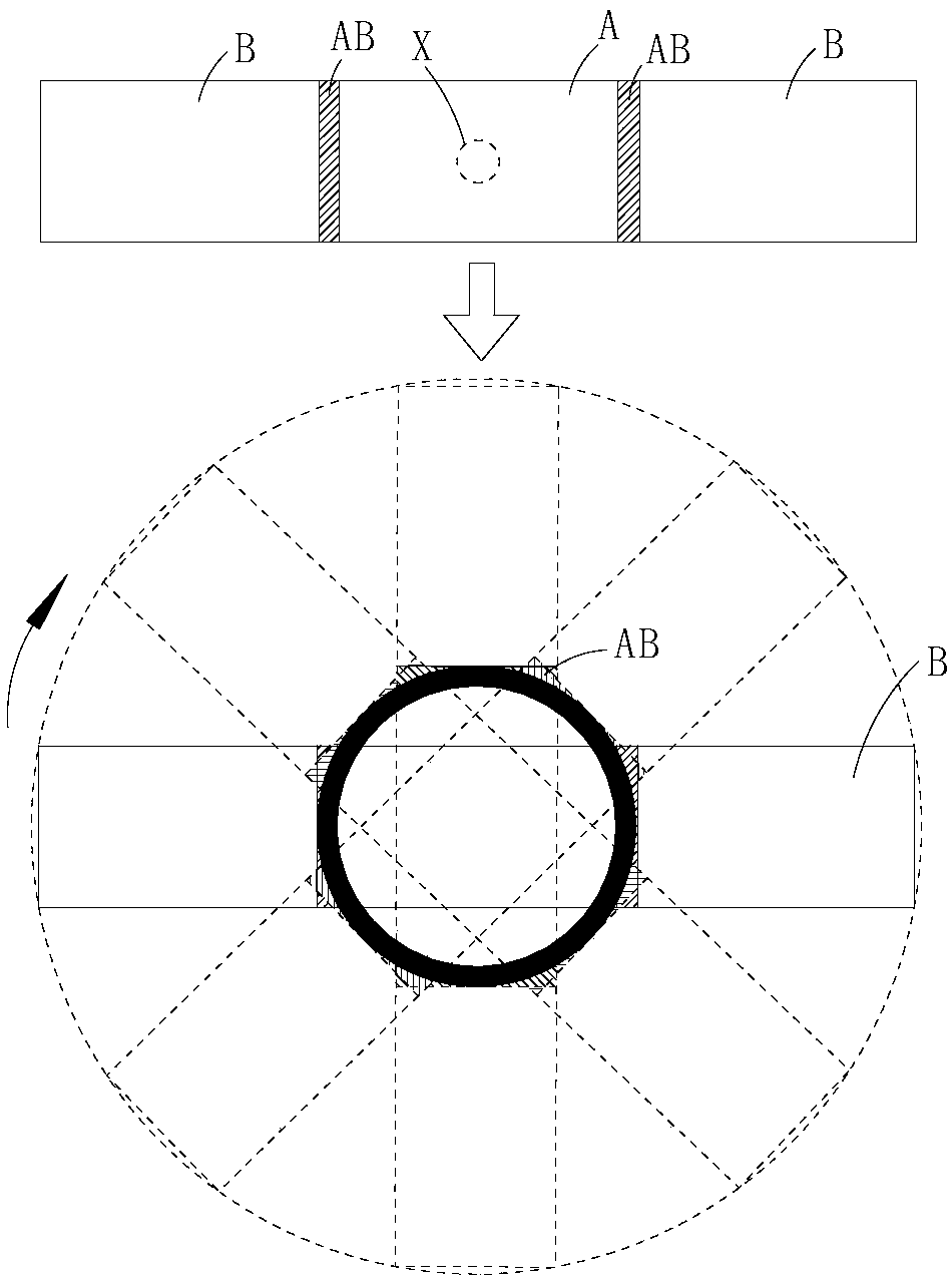
[0004] However, when the screen is spliced, there is a screen frame AB (that is, a splicing seam), and when it is rotated for display, an overlapping dark area will be formed in the frame area, so that the image cannot be displayed in this dark area, resulting in missing or inaccurate images. continuous

Method used


Image

  • Rotary splice screen
  • Rotary splice screen
  • Rotary splice screen

Examples


Embodiment 1

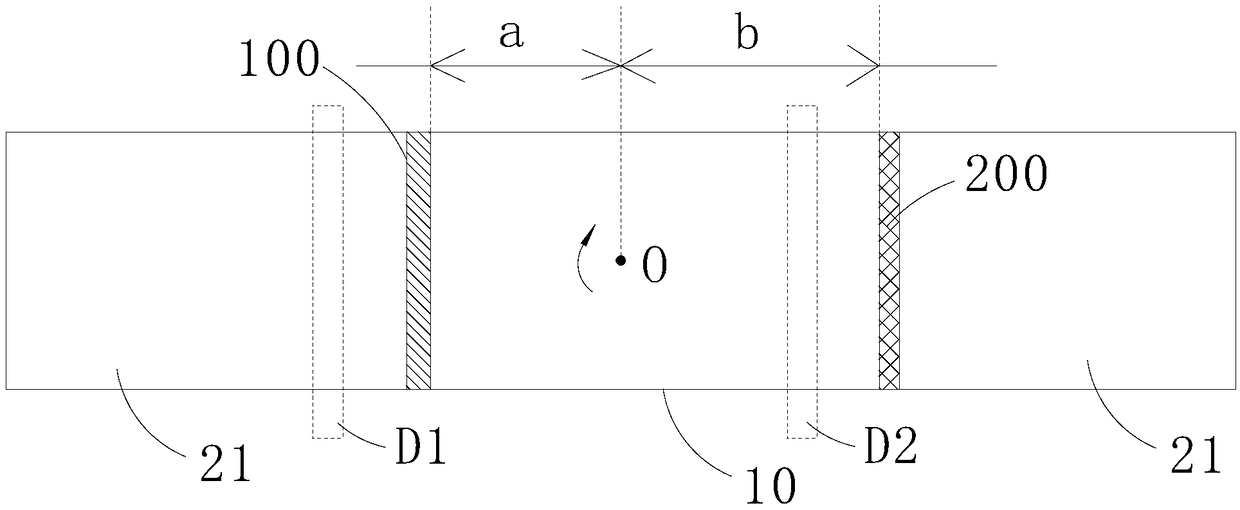
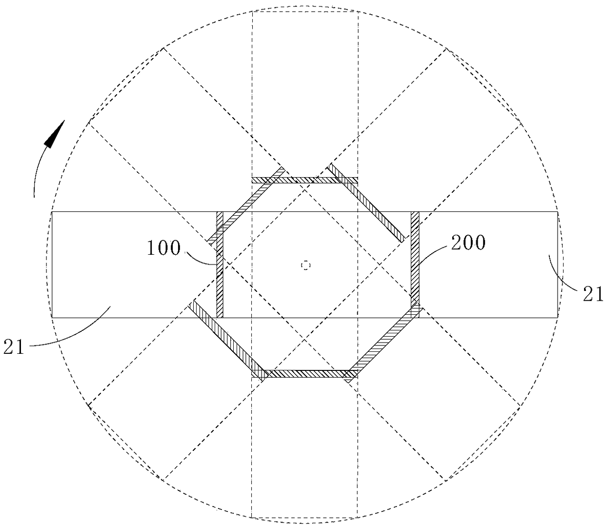
[0026] refer to figure 2 and image 3 The rotary splicing screen of this embodiment includes a central display unit 10 that rotates in a predetermined direction and is spliced ​​on two opposite first sides of the central display unit 10 (ie figure 2 left side shown), second side (i.e. figure 2 Shown on the right side) of the side display unit (not marked), the rotation center O of the rotary splicing screen is located on the center display unit 10; the splicing seam includes the first splicing seam 100 on the first side of the rotation center O and The second seam 200 located on the second side of the rotation center O, the sub-display area used to perform brightness compensation on the opposite side of the seam includes the first display area D1 located on the first side of the rotation center O and the first display area D1 located on the first side of the rotation center O O the second display area D2 on the second side, the rotation trajectory of the second display ar...

Embodiment 2

[0031] Such as Figure 4 As shown, different from Embodiment 1, the side display unit of this embodiment also includes a plurality of second display units 22, and in Embodiment 1, every two adjacent display units are also spliced ​​with one second display unit 22 at the same time , that is, the central display unit 10 and the first display unit 21 are spliced ​​with a second display unit 22 at the same time, and every two first display units 21 are spliced ​​with a second display unit 22 at the same time, as Figure 4 Among them, the first display unit 21 and the center display unit 10 are in the length direction of the display unit (such as Figure 4 The left and right sides of the display unit) are spliced, and the second display unit 22 is spliced ​​in the width direction of the display unit (such as Figure 4The up and down directions in the center) are spliced ​​with the central display unit 10 and the first display unit 21 . It can be understood that there may be multi...


PUM


Abstract

The invention discloses a rotary splicing screen, comprising a central display unit and side display units spliced on two opposite sides of the central display unit. The rotation center of the splicing screen is located on the central display unit. The central display unit and / or each of the side display units includes at least one sub-display area, and each splice seam located on one side of therotation center is rotationally symmetrical with respect to the rotation center with respect to one of the sub-display areas located on the other side of the rotation center, respectively. Since the paths of the stitching seams on both sides of the rotation center do not coincide in the rotation process, no overlapping dark areas are formed, and other non-stitching seam areas of the display unit can be used for brightness compensation, so that the display brightness of the dark areas is consistent with the overall brightness after rotation, so as to realize the complete display of the image content in the circular display area.

Description

technical field [0001] The invention relates to the technical field of rotating screens, in particular to a rotating splicing screen. Background technique [0002] In a specific situation, it is necessary to use a rotating display device to display image content, so as to use a small-area display screen to achieve a larger-area display screen. When a larger screen needs to be displayed, the rotating display screen is often further It is made by splicing multiple screens. [0003] Such as figure 1 As shown, when using multiple screens for multi-screen splicing display, the commonly used method of splicing is to take the center screen A as the center reference, adopt a center-symmetrical method to splice other screens B around the center screen 1, and then make the rotation axis X vertical It is connected to the center of the back of the central screen A to drive the display device to rotate, so that the display device after splicing can have a display effect symmetrical to ...

Claims


Application Information

Patent Timeline
Patent Type & Authority Applications(China)
IPC IPC(8): G09F9/302G09F9/37
CPCG09F9/3026G09F9/37
Inventor 赖庆鸿许神贤
Owner TCL CHINA STAR OPTOELECTRONICS TECH CO LTD
Learn More