Self-aligning safety spiral lifting device

A technology of safety screw and lifting device, which is applied in the direction of lifting device, lifting frame, transmission device, etc., can solve the problems of poor centering accuracy of screw and nut, and the lifting device cannot be lifted and lowered smoothly, and achieve the effect of reducing shaking

Active Publication Date: 2018-12-18
SICHUAN EAST SPRING MACHINERY EQUIP MFG CO LTD
View PDF7 Cites 2 Cited by
  • Summary
  • Abstract
  • Description
  • Claims
  • Application Information

AI Technical Summary

Problems solved by technology

[0003] The invention overcomes the deficiencies of the prior art, provides a self-aligning safety screw lifting device that ensures the accurate alignment of the screw and the nut and ensures the smooth movement of the nut, and solves the problems of the poor centering accuracy of the screw and the nut and the failure of the lifting device. The problem of smooth lifting

Method used


Image

  • Self-aligning safety spiral lifting device
  • Self-aligning safety spiral lifting device
  • Self-aligning safety spiral lifting device

Examples


Embodiment 1

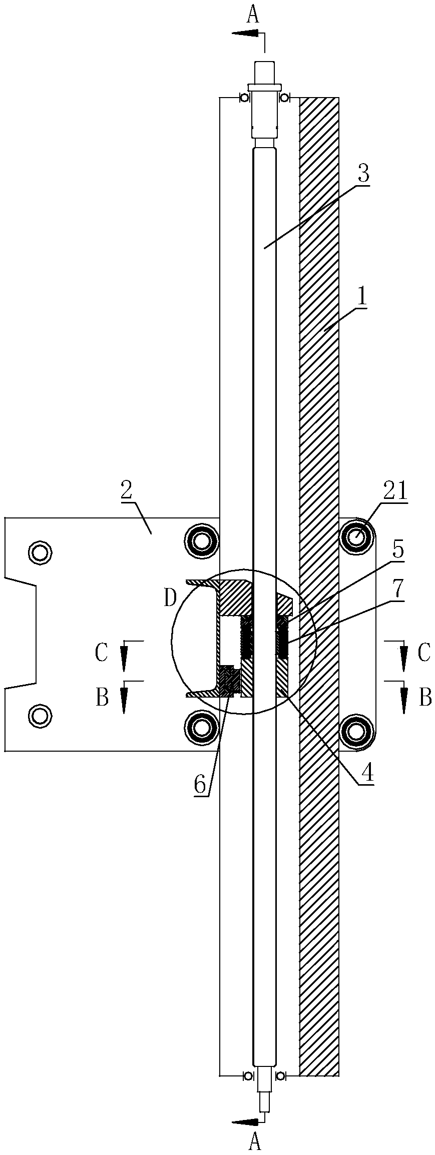
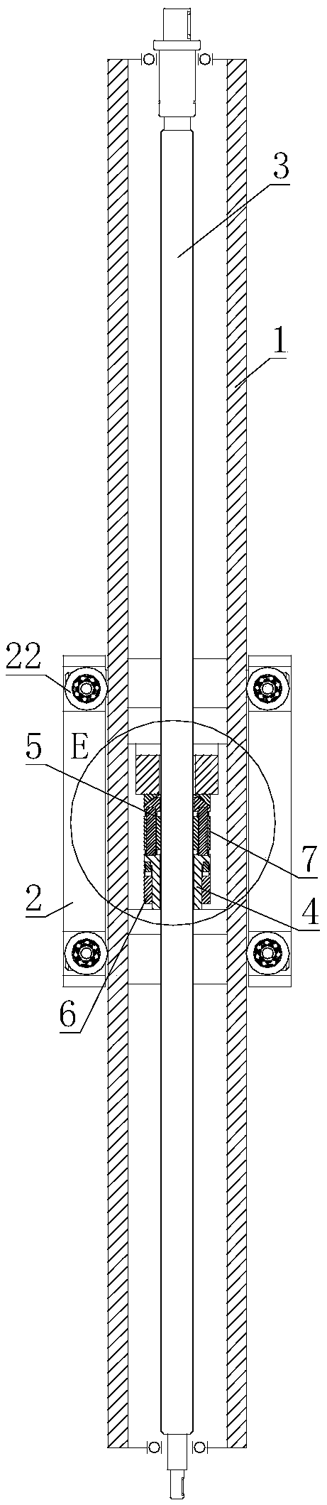
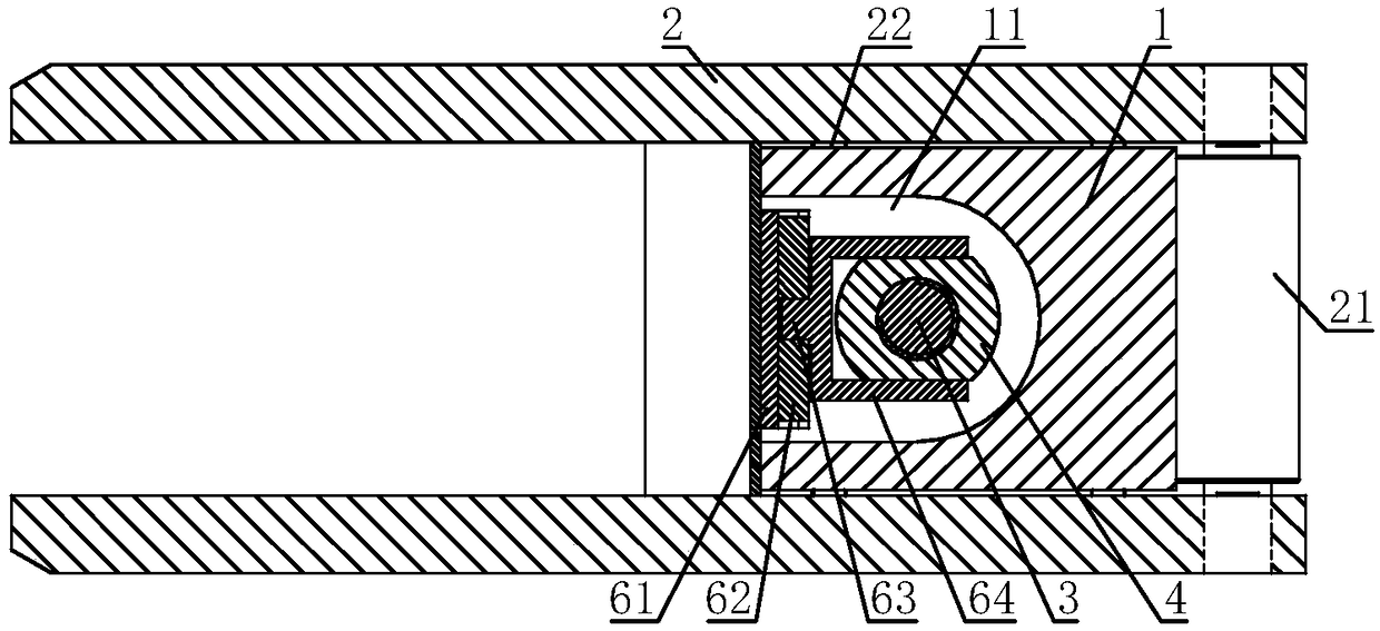
[0030] A self-aligning safety spiral lifting device, including a guiding square column 1, a U-shaped groove 11 is arranged on one side of the guiding square column 1, a nut seat 2 is set on the guiding square column 1, and the nut seat 2 is close to the guiding square column 1 A number of rollers 21 or a number of rollers 22 are installed on the four sides through bearings, and the rollers 21 and rollers 22 are all in contact with the surface of the guide square column 1; , both ends of the screw 3 are connected with the guide column 1 through bearings; the screw 3 is provided with a universal bearing seat mechanism 5, and one end of the universal bearing seat mechanism 5 is fixed on the nut seat 2, and the universal bearing seat mechanism 5 is fixed on the nut seat 2. The other end of the bearing seat mechanism 5 is connected with the nut 4;

[0031] Because the cylinder 21 or the roller 22 around the nut seat 2 contacts with the guide square column 1, when the nut seat 2 til...

Embodiment 2

[0033] On the basis of Embodiment 1, the universal bearing mechanism 5 includes a load-bearing block 51, which is sleeved on the screw 3, and the lower end of the load-bearing block 51 is fixed with a concave spherical seat 52, and the lower end of the concave spherical seat 52 is covered A convex spherical seat 53 is provided, and the concave spherical seat 52 and the convex spherical seat 53 are both sleeved on the lead screw 3. The lower end of the convex spherical seat 53 is fixed with several pillars 54, and the other end of the pillar 54 is connected with the nut 4. Several pillars 54 Evenly distributed on the circle centered on the center line of the nut 4.

[0034] The gravity of the nut seat 2 acts on the nut 4 through the bearing seat 51 , the concave spherical seat 52 , the convex spherical seat 53 and the pillar 54 in sequence. When the nut 4 is slightly offset relative to the lead screw 3, under the obstruction of the concave spherical seat 52, the convex spherica...

Embodiment 3

[0036] On the basis of Embodiment 1 or Embodiment 2, an anti-fall nut 7 is arranged between the convex spherical seat 53 and the nut 4, and the anti-fall nut 7 is threadedly connected with the lead screw 3, and several through-holes are arranged on the anti-fall nut 7. hole, and the pillar 54 is sleeved in the through hole.

[0037] The anti-fall nut 7 lifts together with the nut 4 and does not carry the load when the device works normally, but when the nut 4 fails due to wear, the anti-fall nut 7 bears the axial load to prevent heavy objects from falling, which plays a role of safety protection.


PUM


Abstract

The invention relates to the field of spiral lifting devices, in particular to a self-aligning safety spiral lifting device which comprises a guiding square column. A U-shaped groove is formed in oneside of the guiding square column; a nut seat sleeves on the guiding square column; a plurality of rollers or rolling wheels are arranged on the periphery, close to the guiding square column, of the nut seat through bearings; the rollers and the rolling wheels contact the surface of the guiding square column; a screw rod is sleeved in the U-shaped groove and is in threaded connection with a nut; two ends of the screw rod are connected with the guiding square column through bearings; a universal bearing seat mechanism sleeves on the screw rod; one end of the universal bearing seat mechanism isfixed onto the nut seat; the other end of the universal bearing seat mechanism is connected with the nut; a follow-up torsion seat mechanism is further fixed onto the nut seat; and the other end of the follow-up torsion seat mechanism is clamped on the nut. The invention provides the self-aligning safety spiral lifting device capable of ensuring the accurate alignment of the screw rod and the nutso as to ensure the stable movement of the nut.

Description

technical field [0001] The invention relates to the field of spiral lifting devices, in particular to a self-aligning safety spiral lifting device. Background technique [0002] The spiral lifting method is a common form of short-stroke and medium-short-stroke heavy lifting elevators. The lifting of heavy objects has no special precision requirements for the lifting stroke path. Accurate alignment between the axis of the screw shaft and the nut. When the lead screw and the nut cannot be accurately aligned, the transmission of the nut is blocked, and the lifting device connected with the nut shakes because it is difficult to move smoothly. Contents of the invention [0003] The invention overcomes the deficiencies of the prior art, provides a self-aligning safety screw lifting device that ensures the accurate alignment of the screw and the nut and ensures the smooth movement of the nut, and solves the problems of the poor centering accuracy of the screw and the nut and the...

Claims


Application Information

Patent Timeline
Patent Type & Authority Applications(China)
IPC IPC(8): B66F7/14F16H25/24
CPCB66F7/14F16H25/24F16H2025/2445
Inventor 罗龙聪王会中冷真龙于建
Owner SICHUAN EAST SPRING MACHINERY EQUIP MFG CO LTD
Why Eureka
Try Eureka