A self-aligning safety screw lifting device
A technology of safety screw and lifting device, which is applied in the direction of lifting device, lifting frame, transmission device, etc., can solve the problems of poor centering accuracy of screw and nut, and the lifting device cannot be lifted and lowered smoothly, and achieve the effect of reducing shaking
- Summary
- Abstract
- Description
- Claims
- Application Information
AI Technical Summary
Problems solved by technology
Method used
Image
Examples
Embodiment 1
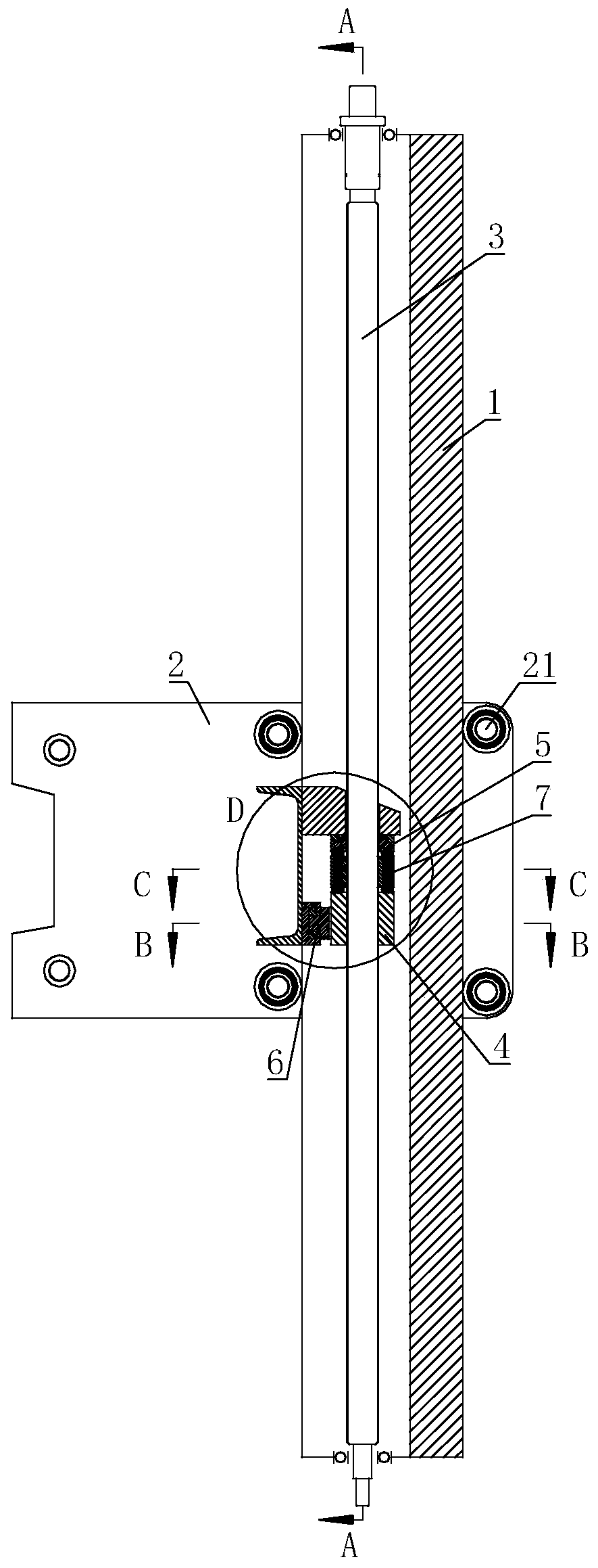
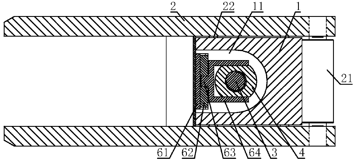
[0030] A self-aligning safety spiral lifting device, including a guiding square column 1, a U-shaped groove 11 is arranged on one side of the guiding square column 1, a nut seat 2 is set on the guiding square column 1, and the nut seat 2 is close to the guiding square column 1 The rollers 21 or rollers 22 are installed on the four sides through the bearings, and the rollers 21 or rollers 22 are in contact with the surface of the guide square column 1; the U-shaped groove 11 is sleeved with a screw 3, and the screw 3 is threaded with a nut 4, and the screw Both ends of 3 are connected with the guide column 1 through bearings; the screw 3 is provided with a universal bearing seat mechanism 5, and one end of the universal bearing seat mechanism 5 is fixed on the nut seat 2, and the universal bearing seat mechanism 5 is fixed on the nut seat 2. The other end of 5 is connected with nut 4; The follow-up torque seat mechanism 6 is also fixed on the nut seat 2, and the other end of the...
Embodiment 2
[0033] On the basis of Embodiment 1, the universal bearing mechanism 5 includes a load-bearing block 51, which is sleeved on the lead screw 3, and the lower end of the load-bearing block 51 is fixed with a concave spherical seat 52, and the lower end of the concave spherical seat 52 is covered A convex spherical seat 53 is provided, the concave spherical seat 52 and the convex spherical seat 53 are both sleeved on the lead screw 3, the lower end of the convex spherical seat 53 is fixed with a pillar 54, the other end of the pillar 54 is connected with the nut 4, and the pillars 54 are evenly distributed On the circle centered on the centerline of the nut 4.
[0034] The gravity of the nut seat 2 acts on the nut 4 through the bearing seat 51 , the concave spherical seat 52 , the convex spherical seat 53 and the pillar 54 in sequence. When the nut 4 is slightly offset relative to the lead screw 3, under the obstruction of the concave spherical seat 52, the convex spherical seat ...
Embodiment 3
[0036] On the basis of Embodiment 1 or Embodiment 2, an anti-fall nut 7 is arranged between the convex spherical seat 53 and the nut 4, and the anti-fall nut 7 is threadedly connected with the lead screw 3, and a through hole is arranged on the anti-fall nut 7 , The pillar 54 is sleeved in the through hole.
[0037] The anti-fall nut 7 lifts together with the nut 4 and does not bear load when the device is working normally, but when the nut 4 fails due to wear, the anti-fall nut 7 bears the axial load and prevents heavy objects from falling, which plays a role of safety protection.
PUM
 Abstract
Description
Claims
Application Information
 - R&D
- Intellectual Property
- Life Sciences
- Materials
- Tech Scout
- Unparalleled Data Quality
- Higher Quality Content
- 60% Fewer Hallucinations
Browse by: Latest US Patents, China's latest patents, Technical Efficacy Thesaurus, Application Domain, Technology Topic, Popular Technical Reports.
© 2025 PatSnap. All rights reserved.Legal|Privacy policy|Modern Slavery Act Transparency Statement|Sitemap|About US| Contact US: help@patsnap.com


