A novel optically controlled microwave oscillator

A microwave oscillator, a new type of technology, applied in power oscillators, resonators, waveguide-type devices, etc., can solve the problems of increased production cost, low control sensitivity, low vibration phase noise, etc., and achieve the effect of simple structure and high sensitivity

Inactive Publication Date: 2018-12-18
UNIV OF ELECTRONICS SCI & TECH OF CHINA ZHONGSHAN INST
View PDF6 Cites 4 Cited by
  • Summary
  • Abstract
  • Description
  • Claims
  • Application Information

AI Technical Summary

Problems solved by technology

[0002] The voltage-controlled oscillator (VCO) is the basic unit of the phase-locked loop in the communication system. Its working principle is to take out a part of the energy at the output of the voltage-controlled oscillator, and after microwave frequency division, it is compared with the reference frequency generated by a crystal oscillator. After phase comparison, the obtained error signal is smoothed and filtered by the loop filter, and is used to control the control voltage of the microwave voltage-controlled oscillator, so that the frequency of the oscillator is locked with the reference frequency, and the frequency stability of the microwave oscillator can be compared with that of the crystal The frequency stability of the oscillator is kept at the same order of magnitude, the effect is good, and the phase noise of the local oscillator is low, but the circuit structure is more complicated, resulting in higher production costs and low control sensitivity

Method used


Image

  • A novel optically controlled microwave oscillator
  • A novel optically controlled microwave oscillator
  • A novel optically controlled microwave oscillator

Examples


Embodiment Construction

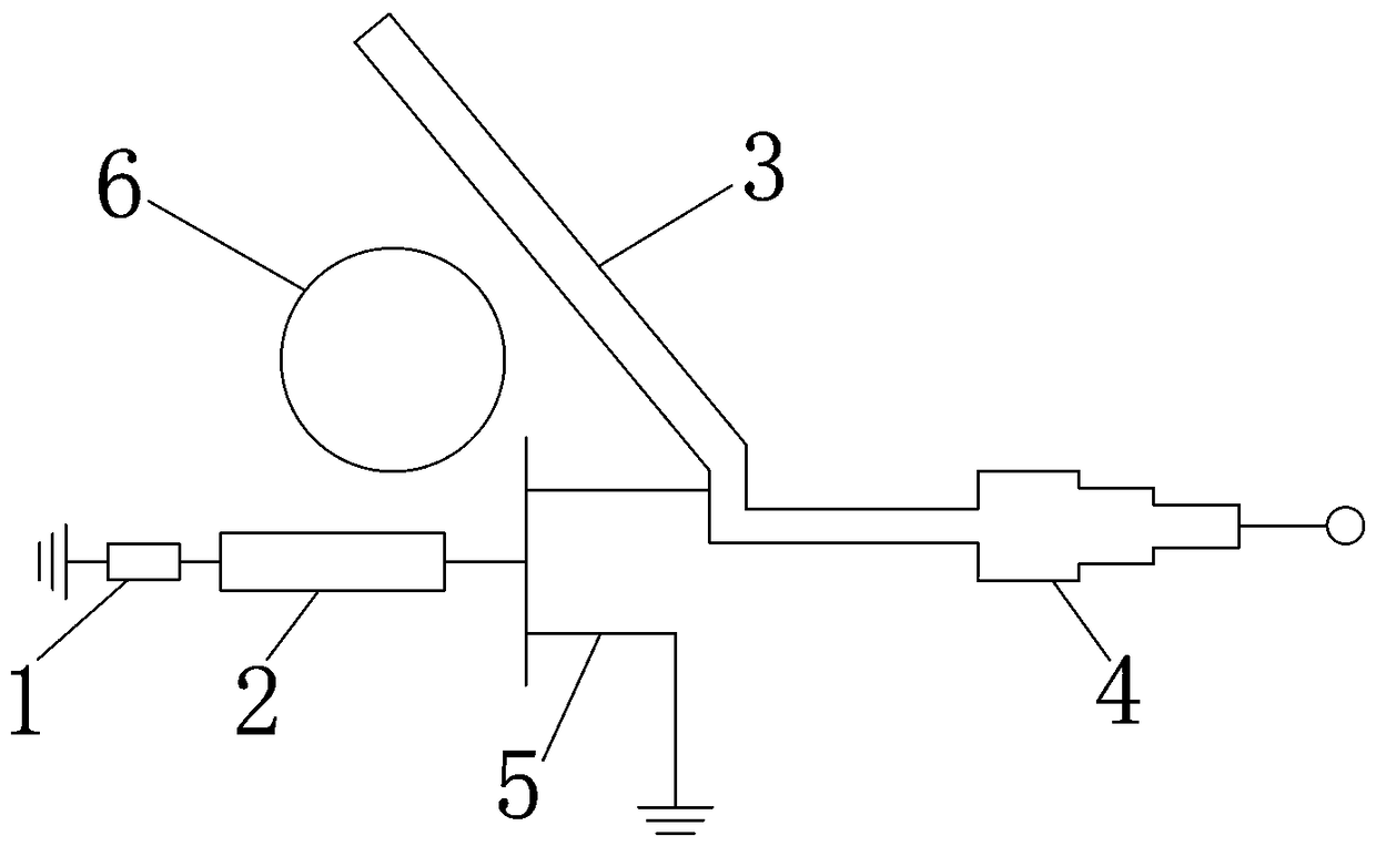
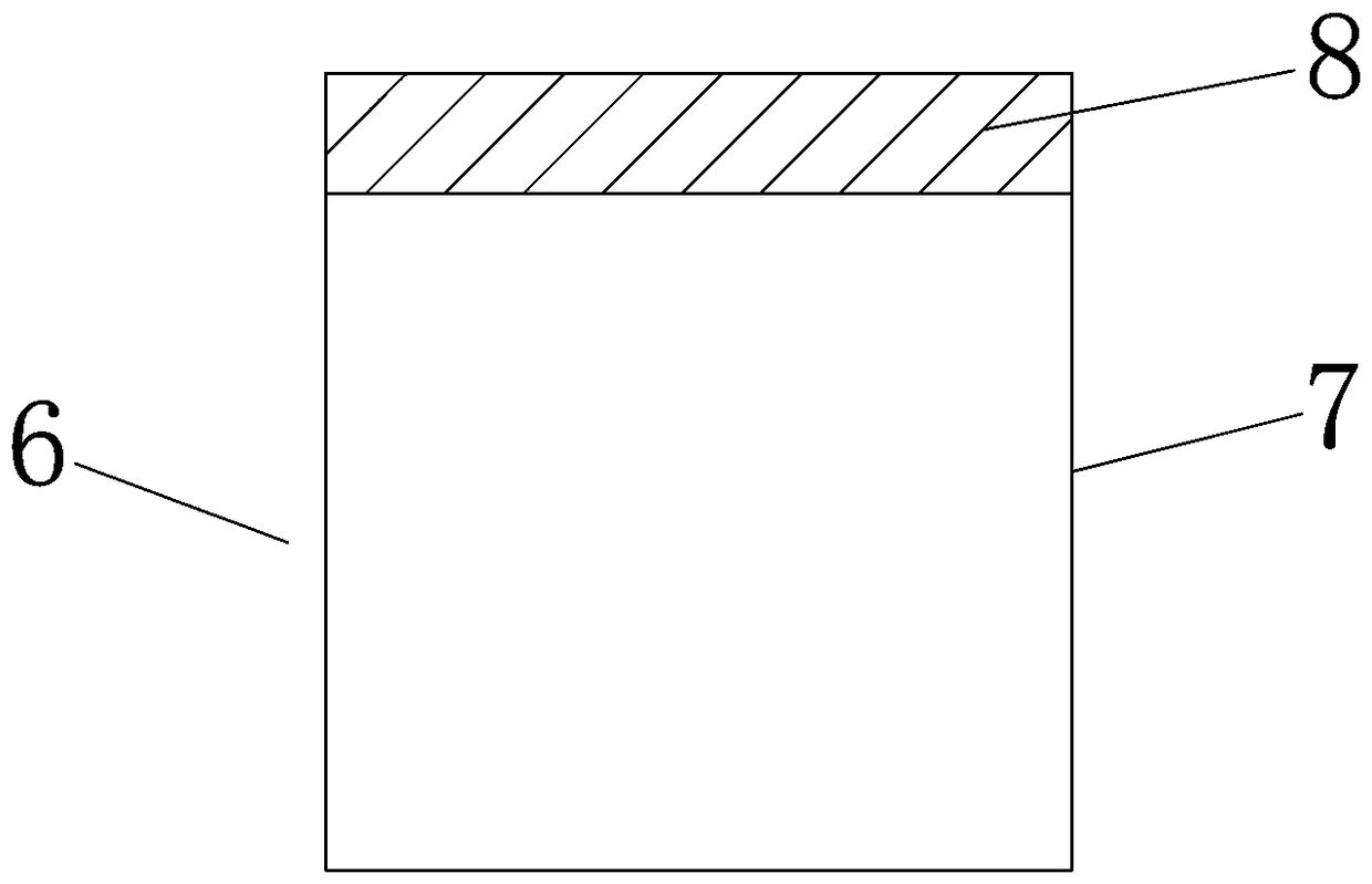
[0011] refer to figure 1 , figure 2 , a novel light-controlled microwave oscillator, comprising a bias resistor 1, a first coupled microstrip circuit 2, a second coupled microstrip circuit 3, an output microstrip circuit 4, a microwave field effect tube 5 and a resonator 6, the The resonator 6 includes a dielectric resonator 7, part or all of the surface of the dielectric resonator 7 is covered with a semiconductor layer 8, and one end of the first coupled microstrip circuit 2 is connected to the gate of the microwave field effect transistor 5, so The other end of the first coupled microstrip circuit 2 is connected to one end of the bias resistor 1, the other end of the bias resistor 1 is grounded, and the drain of the microwave field effect transistor 5 is divided into two paths, one path is connected to the Described second coupled microstrip circuit 3, the other road is connected with one end of the output microstrip circuit 4, the other end of the output microstrip circu...


PUM


Abstract

The invention discloses a novel optically controlled microwave oscillator, including a bias resistor, first coupled microstrip circuit, second coupled microstrip circuit, output microstrip circuit, microwave field effect transistor and resonator, one end of the first coupled microstrip circuit is connected to the grid of the microwave field effect transistor, the other end of the first coupled microstrip circuit is connected to one end of the bias resistor, and the other end of the bias resistor is grounded. The drain of the microwave field effect transistor is divided into two channels, one is connected with the second coupling microstrip circuit, the other is connected with one end of the output microstrip circuit, the other end of the output microstrip circuit is used as the output end,the source of the microwave field effect transistor is grounded, and the resonator is coupled with the first coupling microstrip circuit and the second coupling microstrip circuit at the same time. The resonator is a semiconductor composite dielectric resonator, which can produce a plasma layer when the light is irradiated, so that the resonant frequency of the resonator is changed, thereby changing the working frequency of the whole microwave oscillator and realizing the control of the microwave oscillator. The structure is simple and the sensitivity is high.

Description

technical field [0001] The invention relates to a microwave oscillator, in particular to a light-controlled microwave oscillator. Background technique [0002] The voltage-controlled oscillator (VCO) is the basic unit of the phase-locked loop in the communication system. Its working principle is to take out a part of the energy at the output of the voltage-controlled oscillator, and after microwave frequency division, it is compared with the reference frequency generated by a crystal oscillator. After phase comparison, the obtained error signal is smoothed and filtered by the loop filter, and is used to control the control voltage of the microwave voltage-controlled oscillator, so that the frequency of the oscillator is locked with the reference frequency, and the frequency stability of the microwave oscillator can be compared with that of the crystal The frequency stability of the oscillator is maintained at the same order of magnitude, the effect is good, and the phase noi...

Claims


Application Information

Patent Timeline
Patent Type & Authority Applications(China)
IPC IPC(8): H03B1/02H01P7/10
CPCH01P7/10H03B1/02
Inventor 喻志远徐立周李梦男陈东佛邓春健
Owner UNIV OF ELECTRONICS SCI & TECH OF CHINA ZHONGSHAN INST
Why Eureka
Try Eureka