A dynamic design method for high-speed electric spindle rotor-bearing-housing system

A high-speed motorized spindle and system dynamics technology, applied in design optimization/simulation, computer-aided design, calculation, etc., can solve problems such as misleading motorized spindle dynamic design, large error in the calculation result of the critical speed of the motorized spindle rotor, and time-consuming solution. Achieve the effect of shortening the R&D cycle, improving the dynamic design accuracy, and reducing the design risk

Active Publication Date: 2019-10-15
SOUTHEAST UNIV
View PDF5 Cites 0 Cited by
  • Summary
  • Abstract
  • Description
  • Claims
  • Application Information

AI Technical Summary

Problems solved by technology

[0003] For the above-mentioned high-speed electric spindle, there are mainly two methods of processing the shell at home and abroad: (1) The electric spindle rotor-bearing-shell system is regarded as a static cantilever beam, and this method can calculate the static stiffness of the rotor shaft end through deflection analysis , but ignores the bearing stiffness softening effect and rotor gyro effect caused by high speed, the calculation result of the critical speed of the electric spindle rotor has a large error, and there is a risk of misleading the dynamic design of the electric spindle; (2) Use commercial software to establish a three-dimensional model of the electric spindle , and then analyze its dynamic characteristics in the simulation module. This method also ignores the bearing stiffness softening effect and rotor gyro effect caused by high speed, and the calculation accuracy is low; at the same time, the modeling process is complex and cumbersome, and the solution is time-consuming, which is not conducive to the development Sensitivity Design of Rotor Dynamics Characteristics of Electric Spindle

Method used


Image

  • A dynamic design method for high-speed electric spindle rotor-bearing-housing system
  • A dynamic design method for high-speed electric spindle rotor-bearing-housing system
  • A dynamic design method for high-speed electric spindle rotor-bearing-housing system

Examples


Embodiment Construction

[0069] A method for dynamic design of a high-speed electric spindle rotor-bearing-housing system of the present invention will be further described in detail in conjunction with an embodiment (MK2860 / 1-91 electric spindle for internal grinding machine).

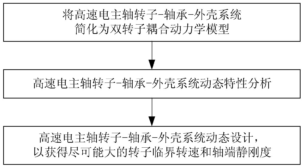
[0070] figure 1 The specific content of a dynamic design method for a high-speed electric spindle rotor-bearing-housing system of the present invention is given, including the following steps:

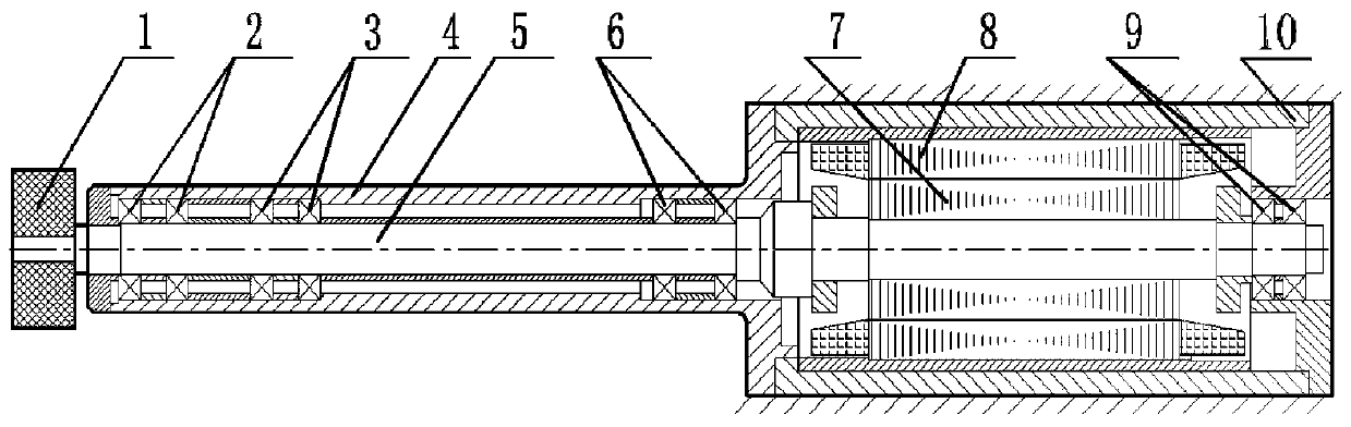
[0071] Step 1: If figure 2 The structure of the high-speed electric spindle shown is: the main shaft rotor 5 adopts four pairs of rolling bearings 2, 3, 6 and 9 to be installed in the casing 4 and the shaft sleeve 10, wherein the first three pairs of rolling bearings 2, 3 and 6 are located in the casing 4 Inside, the fourth pair of rolling bearings 9 is located in the shaft sleeve 10, the housing 4 is fixed on the front end of the shaft sleeve 10 in the form of a cantilever single support, the grinding wheel 1 is installed at the en...


PUM


Abstract

The invention provides a high-speed electric spindle rotor-bearing-housing system dymatic design method. The method comprises the follow steps: step 1, simplifying the high-speed electric spindle rotor-bearing-housing system into double-rotor coupling kinetic model; Step 2: performing high-speed motor spindle rotor-bearing-shell system dynamic characteristic analysis; Step 3: rotor-bearing-shellsystem of high-speed electric spindle is designed dynamically to obtain the maximum rotor critical speed and static stiffness at the shaft end. The high-speed electric spindle rotor-bearing-shell system dynamic design method provided by the invention is adopted , which can greatly improve the dynamic design accuracy of this kind of motorized spindle, and shorten the design cycle, which provides an effective method for the design of this kind of high-speed motorized spindle.

Description

technical field [0001] The invention relates to a dynamic design method for a high-speed electric spindle rotor-bearing-shell system, belonging to the field of high-speed cutting machine tool spindle unit design. Background technique [0002] High-speed precision electric spindle is especially suitable for deep hole processing (such as internal grinding). Motorized spindles for deep hole processing generally adopt a rear-mounted motor layout to reduce the radial dimension of the shaft end. Due to the small outer diameter of the motorized spindle shell and the long overhang, when installed on the machine tool, only the motor end can be clamped, resulting in an ultra-long cantilever structure of the motorized spindle and its tools, which greatly reduces the shaft end of the motorized spindle Stiffness and critical speed of the rotor system. From the perspective of rotor dynamics, this type of electric spindle belongs to the rotor-bearing-housing coupled rotor system. Theref...

Claims


Application Information

Patent Timeline
Patent Type & Authority Patents(China)
IPC IPC(8): G06F17/50
CPCG06F30/17G06F30/20G06F2119/06
Inventor 蒋书运林圣业
Owner SOUTHEAST UNIV
Why Eureka
Try Eureka