Display workstation for desktop
A workstation and display technology, applied in the field of office and learning equipment, can solve the problems of inconvenient electric plugging process, messy power cord plugging, messy desktop, etc., and achieve the effects of clean desktop, avoiding potential safety hazards, and convenient use
Pending Publication Date: 2018-12-28
LOCTEK ERGONOMIC TECH CORP
View PDF8 Cites 3 Cited by
- Summary
- Abstract
- Description
- Claims
- Application Information
AI Technical Summary
Problems solved by technology
However, the above prior art is used for desktop display workstations, and the above devices can only be installed sporadically, and the plugging of the power cords is very messy. , and the electrical plugging process is very inconvenient, and the staggered wires also make the desktop look messy, and there may even be a safety hazard of electric leakage when used for a long time
Method used
View moreImage
Smart ImageViewing Examples

Examples
specific Embodiment
Login to view more PUM
 Abstract
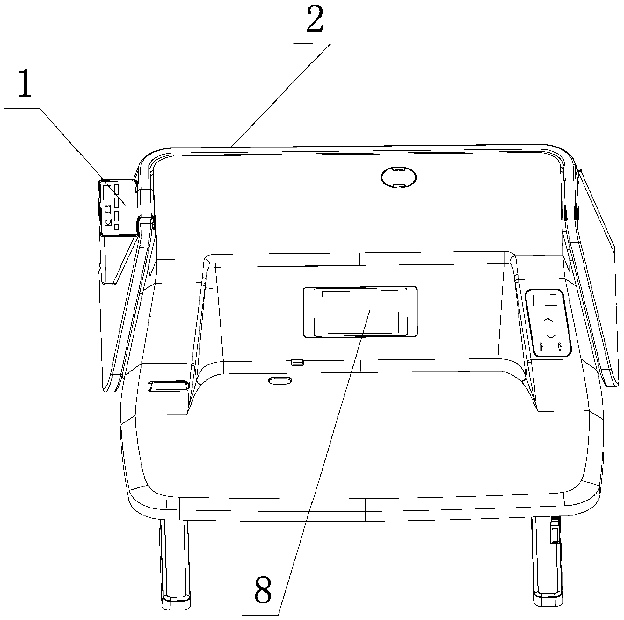
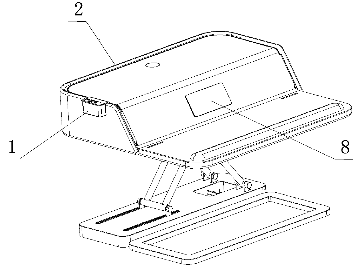
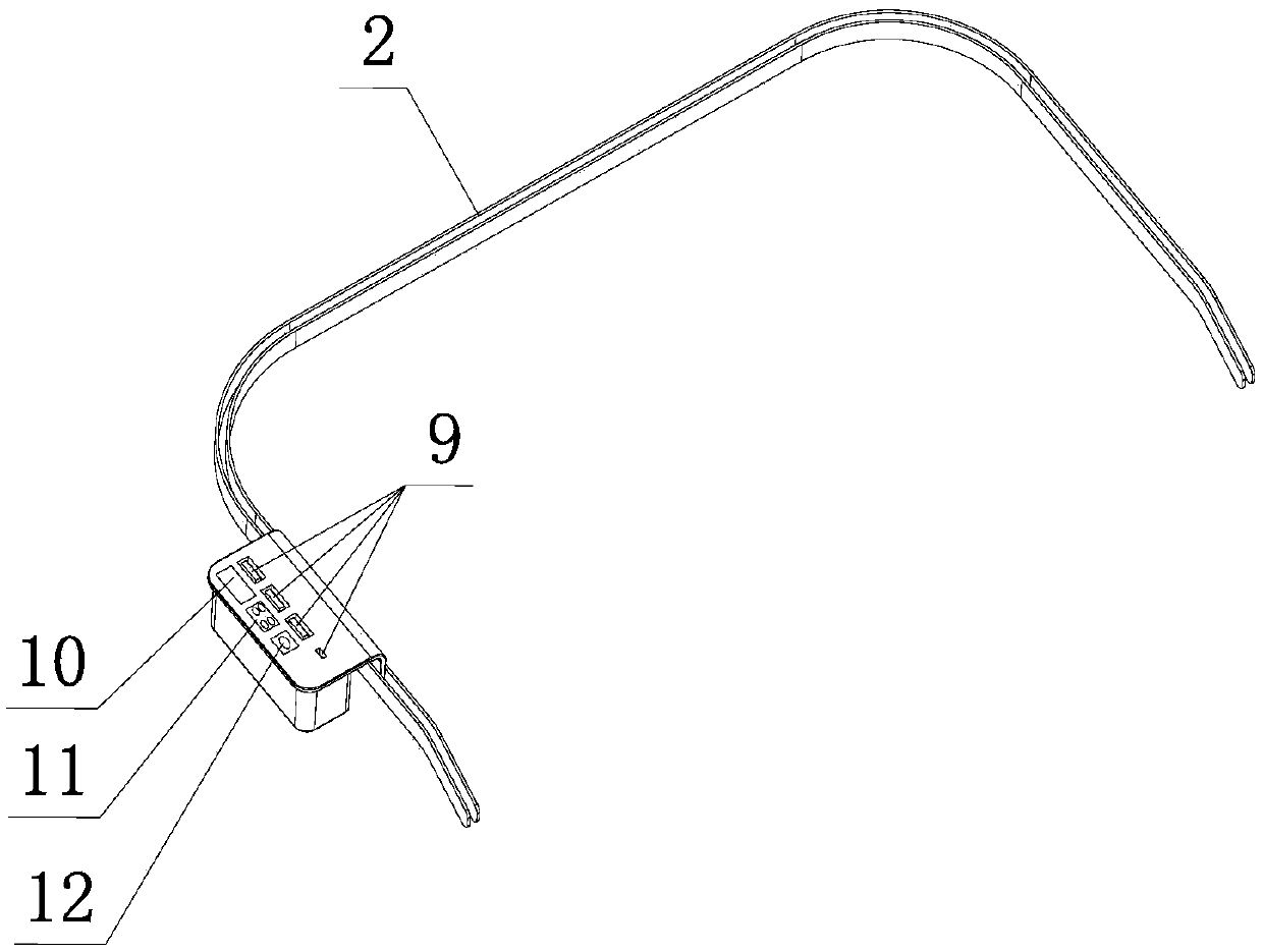
Disclosed is a display workstation for a desktop, including an expansion module for connecting to a power module within a display workstation. At the peripheral edge of the display workstation, a detachable connection structure is provided for the multi-interface expansion module to be placed at different position of the peripheral edge, if the edge is provided with a sliding groove formed by twoguide rails and extending along the peripheral edge, the turning point of the sliding groove is arc transition, the expansion module is hung on the outer guide rails and can slide along the sliding groove to the desired position, and the expansion module and the guide rails can still be connected with a power supply when sliding. As the expansion module can be detachably connected with the peripheral edge of the display workstation at any position. The technical scheme avoids the interleaving of wires, so that the expansion module can meet the various needs of people when working, and the equipment can be in a better position and a better angle, the use is convenient and the desktop is tidy, and the potential safety hazard of electric leakage is basically avoided when the equipment is usedfor a long time.
Description
technical field The invention relates to the technical field of office and learning equipment, in particular to a display workstation for a desktop. Background technique A monitor workstation for a desktop can also be called a monitor workbench for a desktop. In practical applications, a monitor or a notebook computer is generally placed on the workbench. With the popularization of office and learning equipment automation, people have more and more requirements for office and learning equipment. For example, monitor workstations for desktops, in addition to meeting the basic power supply needs of monitors or notebook computers, also hope to meet people's needs for mobile phones and other wireless devices. Charging, the application of USB interface, negative ion generator, speaker, desk lamp, fan and other equipment needs. However, the above prior art is used for desktop display workstations, and the above devices can only be installed sporadically, and the plugging of the...
Claims
Login to view more Application Information
Patent Timeline
 Patent Type & Authority Applications(China)
IPC IPC(8): G06F1/16G06F1/18
CPCG06F1/1601G06F1/189G06F1/1632G06F1/1607
Inventor 项乐宏林涛李方圆
Owner LOCTEK ERGONOMIC TECH CORP
- R&D Engineer
- R&D Manager
- IP Professional
Why Eureka
- Industry Leading Data Capabilities
- Powerful AI technology
- Patent DNA Extraction
Try Eureka
Browse by: Latest US Patents, China's latest patents, Technical Efficacy Thesaurus, Application Domain, Technology Topic.
© 2024 PatSnap. All rights reserved.Legal|Privacy policy|Modern Slavery Act Transparency Statement|Sitemap