Control method and control system of vehicle-mounted camera

A control method and technology of a control system, which are applied in vehicle components, optical observation devices, transportation and packaging, etc., can solve the problems of not meeting the visual field observation requirements, and not being able to accurately obtain the full field of view of an oncoming vehicle on the right, so as to improve safety. Effect

Active Publication Date: 2019-01-04
SHANGHAI YUXING ELECTRONICS TECH CO LTD
View PDF12 Cites 6 Cited by
  • Summary
  • Abstract
  • Description
  • Claims
  • Application Information

AI Technical Summary

Problems solved by technology

However, in the electronic rearview mirrors currently used in vehicles, the camera is fixedly installed on the vehicle body, so the field of view of the camera is fixed. In special situations, such as when turning at an intersection, the fixed right rear view camera cannot accurately obtain The full field of view of the vehicle coming from the right, therefore, a camera with a fixed field of view cannot meet the needs of field of view observation in many scenarios in driving

Method used


Image

  • Control method and control system of vehicle-mounted camera
  • Control method and control system of vehicle-mounted camera
  • Control method and control system of vehicle-mounted camera

Examples


Embodiment Construction

[0052] The present invention will be further described in detail below in conjunction with the accompanying drawings and embodiments. It should be understood that the specific embodiments described here are only used to explain the present invention, but not to limit the present invention. In addition, it should be noted that, for the convenience of description, only some structures related to the present invention are shown in the drawings but not all structures.

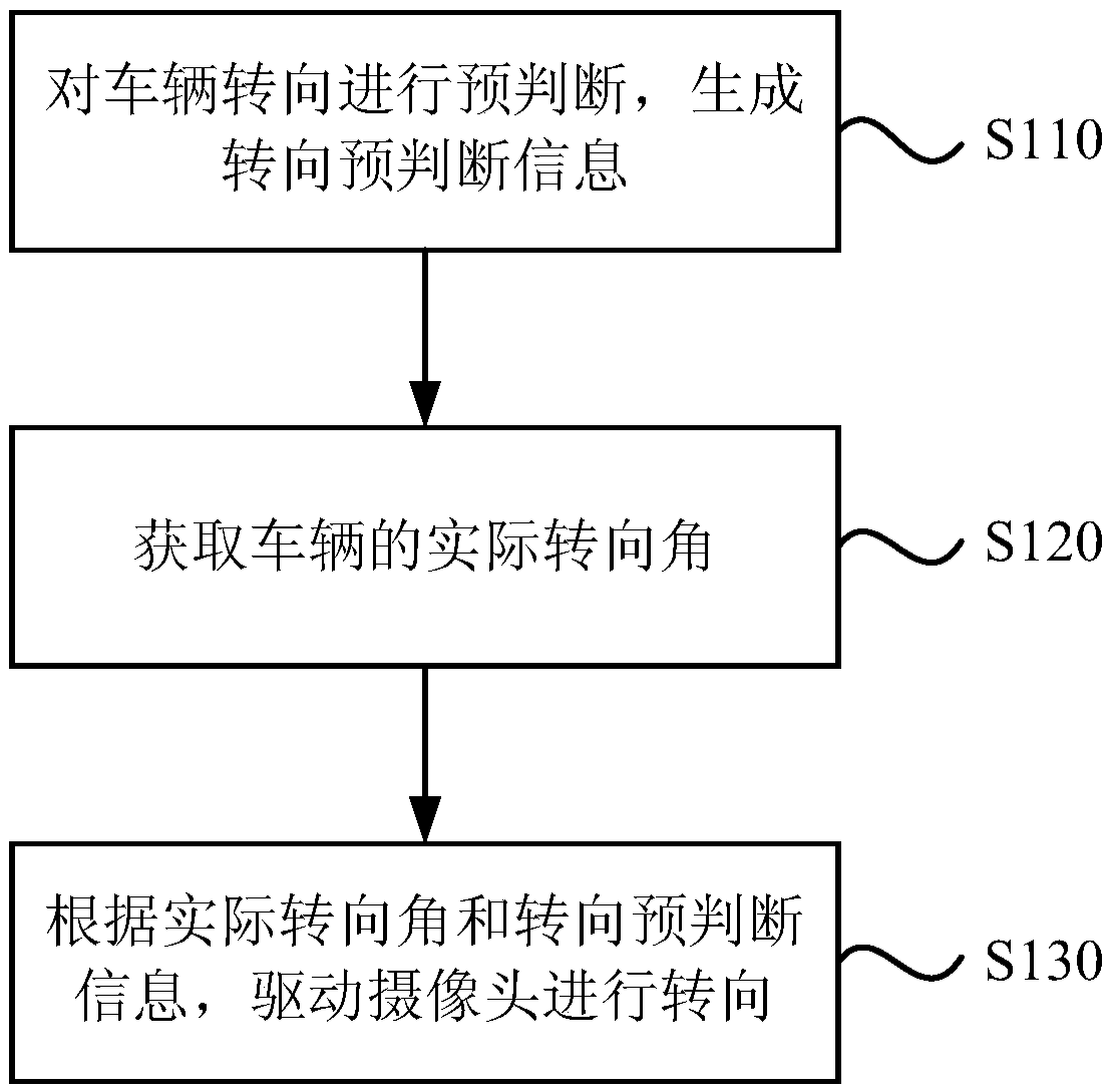
[0053] figure 1 For the flow chart of a method for controlling a vehicle-mounted camera provided by an embodiment of the present invention, refer to figure 1 , the control method of the vehicle camera includes:

[0054] S110, pre-judging the steering of the vehicle, and generating steering pre-judgment information;

[0055] Among them, when the vehicle is driving, the field of view that the driver needs to observe when turning to drive will change significantly compared with that of straight driving. Therefore, ...


PUM


Abstract

The invention discloses a control method and a control system of a vehicle-mounted camera. The control method of the vehicle-mounted camera comprises the following steps of: pre-judging the vehicle steering to generate steering pre-judging information; obtaining the actual steering angle of the vehicle; and driving the camera to steer according to the actual steering angle and the steering pre-judgment information. The invention can obtain the field of view satisfying the observation demand by driving the camera to steer under the vehicle steering scenario, thereby solves the problem that thefield of view collected by the camera in the fixed field of view direction has the observation blind area under the steering scenario, can effectively assist the driver to observe the steering field of view, and contributes to improving the driving safety.

Description

technical field [0001] Embodiments of the present invention relate to the technical field of vehicle safety, and in particular, to a method and system for controlling a vehicle camera. Background technique [0002] Conventional cars are equipped with rearview mirrors on the left and right sides of the car and inside the car to provide visual information on the left, right and rear sides of the car. However, traditional rearview mirrors have many blind spots and cannot meet the observation needs. [0003] The electronic rearview mirror uses the camera to capture the image information around the vehicle, and usually uses a display screen to display the image collected by the camera to obtain the image information of the blind area to meet the driver's observation needs. However, in the electronic rearview mirrors currently used in vehicles, the camera is fixedly installed on the vehicle body, so the field of view of the camera is fixed. In special situations, such as when turn...

Claims


Application Information

Patent Timeline
Patent Type & Authority Applications(China)
IPC IPC(8): B60R1/00
CPCB60R1/00B60R2300/101
Inventor 刘拾玉杜伟光付兵凯
Owner SHANGHAI YUXING ELECTRONICS TECH CO LTD
Why Eureka
Try Eureka