
Corridor control switch

A technology for controlling switches and corridors, applied in electrical switches, electrical components, circuits, etc., can solve problems such as inconvenient control of corridor switches, and achieve the effect of ensuring continuous lighting

Active Publication Date: 2019-01-04
浙江润成合金材料科技有限公司
View PDF9 Cites 0 Cited by
  • Summary
  • Abstract
  • Description
  • Claims
  • Application Information

AI Technical Summary

Problems solved by technology

[0004] The purpose of the present invention is to solve the problem of inconvenient control of the corridor switch, and propose a corridor control switch

Method used

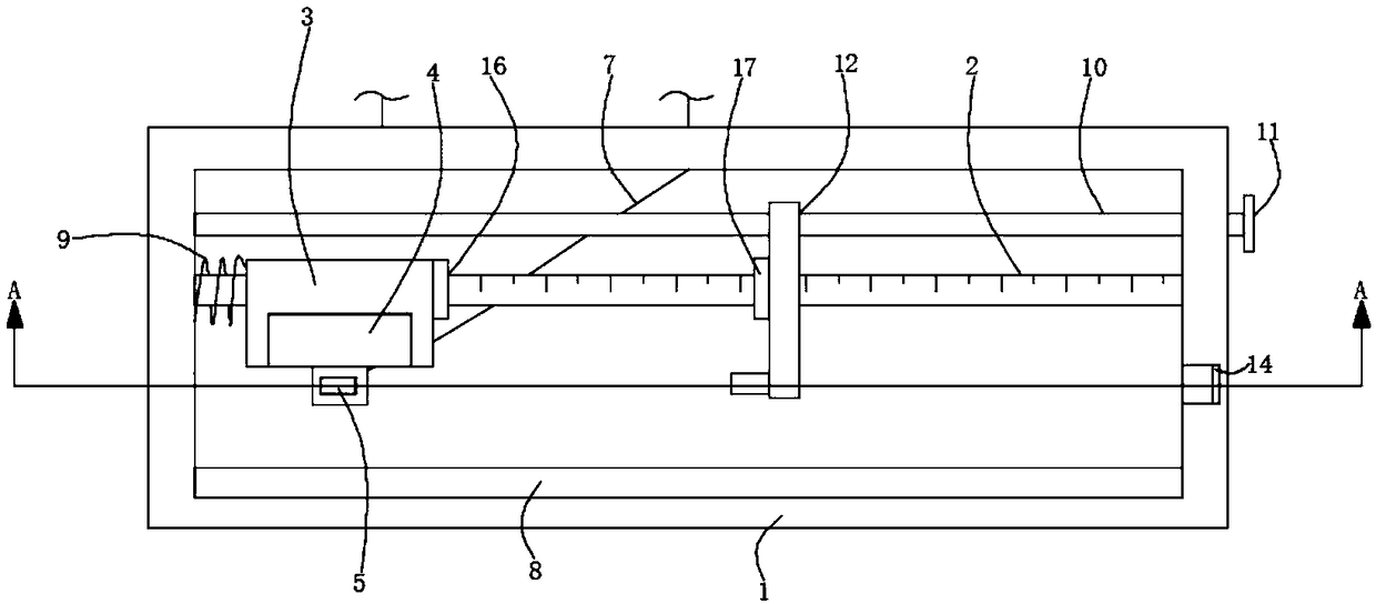
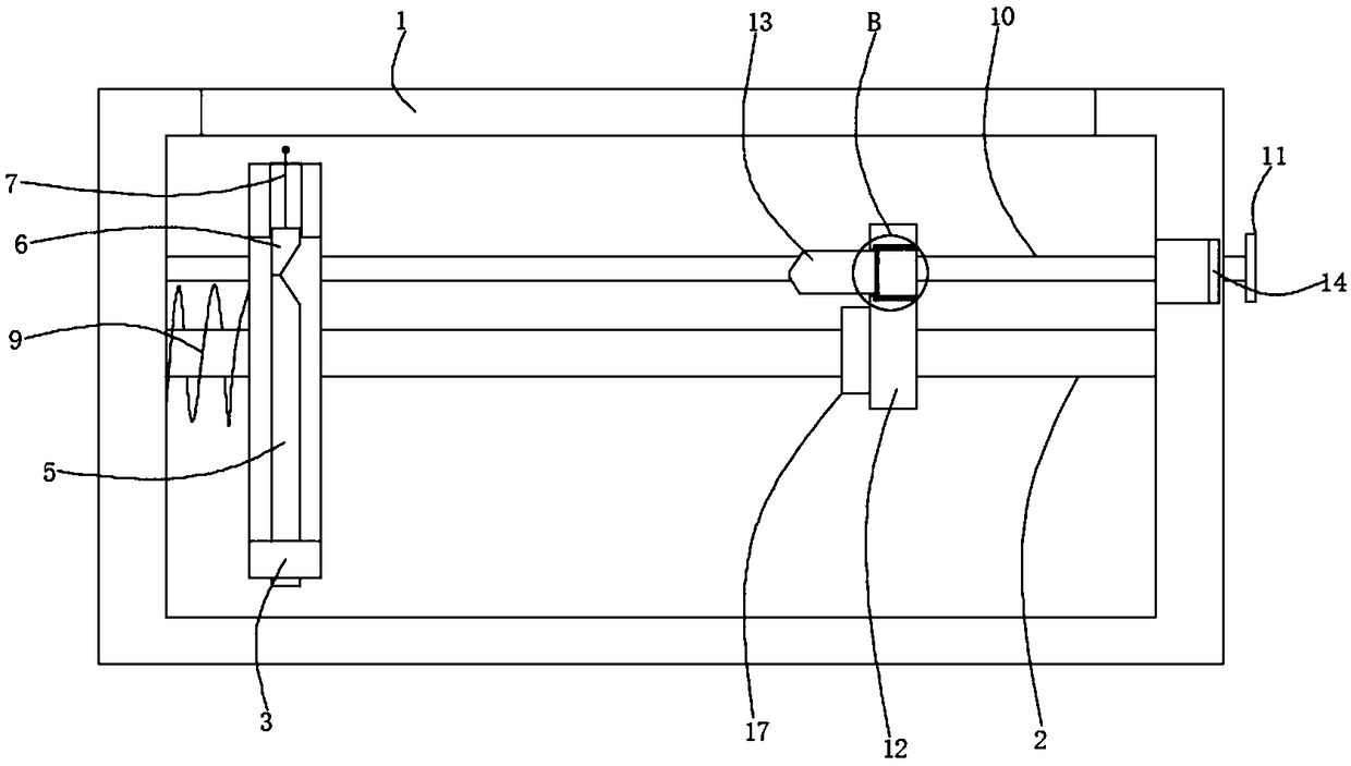
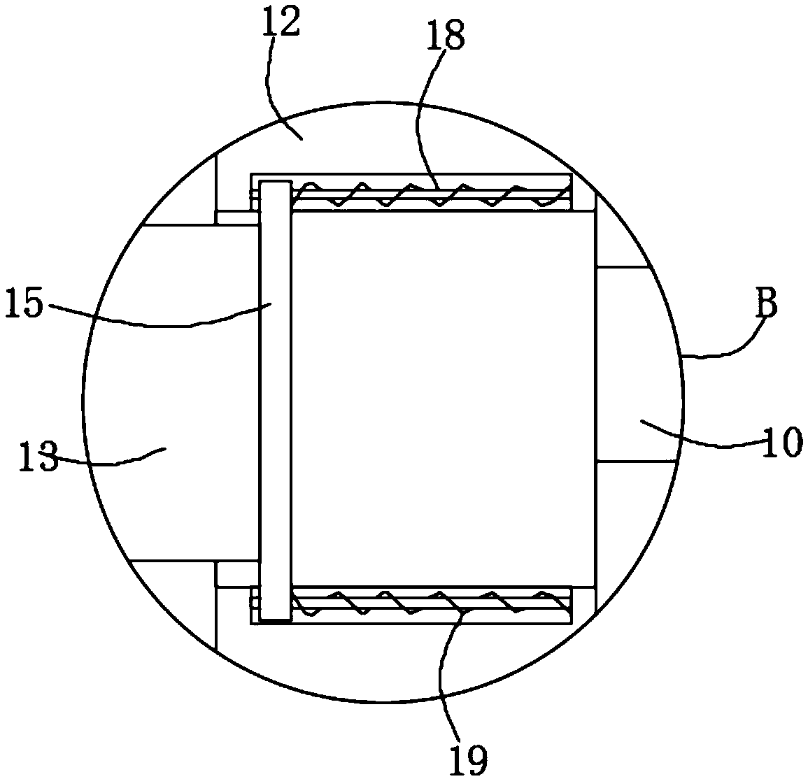

Image

  • Corridor control switch
  • Corridor control switch
  • Corridor control switch

Examples


Embodiment Construction

[0016] The following will clearly and completely describe the technical solutions in the embodiments of the present invention with reference to the accompanying drawings in the embodiments of the present invention. Obviously, the described embodiments are only some, not all, embodiments of the present invention.

[0017] In describing the present invention, it should be understood that the terms "upper", "lower", "front", "rear", "left", "right", "top", "bottom", "inner", " The orientation or positional relationship indicated by "outside", etc. is based on the orientation or positional relationship shown in the drawings, and is only for the convenience of describing the present invention and simplifying the description, rather than indicating or implying that the referred device or element must have a specific orientation, so as to Specific orientation configurations and operations, therefore, are not to be construed as limitations on the invention.

[0018] refer to Figure ...


PUM


Abstract

A corridor control switch Includes fixing cover, the fixing cover is fixedly connected with a horizontal prism-shaped graduation bar, the outer side wall of the calibration rod is slidably sleeved with an insulating U-shaped block, The calibration rod is sleeved with a second spring, the two ends of the second spring are fixedly connected with the inner side wall of the fixed cover and the outer side wall of the insulating U-shaped block, the inner side wall of the insulating U-shaped block is fixedly connected with a first magnet, and the insulating U-shaped block is fixedly connected with the first conductive block. The invention drives the movement of the adjusting block by rotating the handle, the position of the adjustment block on the scale bar can be adjusted according to the lengthof time spent on the corridor, When the first conductive block and the second conductive block are accelerated forward with a reduced acceleration under the action of the magnetic field, the movementis stopped until the first conductive block and the second conductive block move to the squeeze block, thereby automatically turning off the switch of the lighting lamp, and wherein the movement timeis the same as the position of the adjusting block on the scale lever.

Description

technical field [0001] The invention relates to the technical field of checkpoint equipment, in particular to a corridor control switch. Background technique [0002] At present, most of the switches used are push-type, that is, the closing of the switch is controlled by people's pressing, but it often happens that people forget to turn off the switch on the corridor and the light is always on, resulting in a waste of electricity. For this reason, a voice-activated switch has appeared. The voice-activated switch is a switch controlled by voice, but the current voice-activated switch is short-lived. This affects people's use very much. [0003] For this reason, we have designed a kind of corridor control switch. Contents of the invention [0004] The purpose of the present invention is to solve the problem of inconvenient control of the corridor switch, and propose a corridor control switch. [0005] In order to achieve the above object, the present invention adopts the ...

Claims


Application Information

Patent Timeline
Patent Type & Authority Applications(China)
IPC IPC(8): H01H7/08
CPCH01H7/08
Inventor 耿华复
Owner 浙江润成合金材料科技有限公司
Learn More