Supercharge Your Innovation With Domain-Expert AI Agents!

Channel state indication method and device of optical module

A channel status and optical module technology, applied in the field of optical modules, can solve the problems of cumbersome and complicated inspection process, and achieve the effect of simple and convenient inspection process

Active Publication Date: 2019-01-04
HISENSE BROADBAND MULTIMEDIA TECH
View PDF13 Cites 0 Cited by
  • Summary
  • Abstract
  • Description
  • Claims
  • Application Information

AI Technical Summary

Problems solved by technology

[0004] In view of this, the present application provides an optical module channel state indication method and device to solve the problem of cumbersome and complicated optical module channel state inspection process in the related art

Method used


Image

  • Channel state indication method and device of optical module
  • Channel state indication method and device of optical module
  • Channel state indication method and device of optical module

Examples


Embodiment Construction

[0020] Reference will now be made in detail to the exemplary embodiments, examples of which are illustrated in the accompanying drawings. When the following description refers to the accompanying drawings, the same numerals in different drawings refer to the same or similar elements unless otherwise indicated. The implementations described in the following exemplary embodiments do not represent all implementations consistent with this application. Rather, they are merely examples of apparatuses and methods consistent with aspects of the present application as recited in the appended claims.

[0021] The terminology used in this application is for the purpose of describing particular embodiments only, and is not intended to limit the application. As used in this application and the appended claims, the singular forms "a", "the", and "the" are intended to include the plural forms as well, unless the context clearly dictates otherwise. It should also be understood that the term...


PUM


Abstract

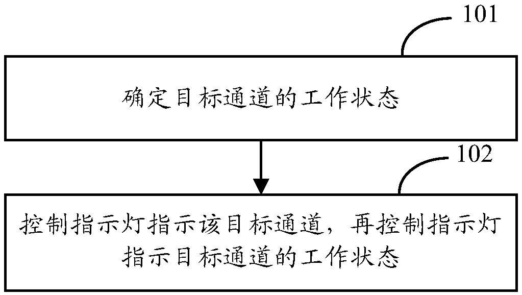
The invention provides a channel state indication method and device of an optical module. The method is applied to the optical module, used for electrical connection between an indicating lamp for indicating the channel state and a circuit board of the optical module, and comprises that the working state of a target channel is determined, the indicating lamp is controlled to indicate the target channel, and the indicating lamp is then controlled to indicate the working state of the target channel. Thus, a user can know the channel state by observing the channel state, and channel state detection is simple and convenient.

Description

technical field [0001] The present application relates to the field of optical module technology, and in particular to a method and device for indicating channel status of an optical module. Background technique [0002] As the application of high-speed optical modules becomes more and more widespread, the number of channels of optical modules is also increasing, such as 4-channel optical modules with 100G rate and 8-channel optical modules with 400G rate. Usually, when troubleshooting an optical module, you first need to check whether the working status of each channel is normal or not. [0003] At present, a separate device (such as a PC) is usually required to access the system interface of the optical module through the local end or terminal of the optical module, and input test instructions for each channel to check whether the working status of each channel is normal or not. no. Since the user needs to input a corresponding test command for each channel to check its ...

Claims


Application Information

Patent Timeline
IPC IPC(8): H04B10/073
CPCH04B10/0731
Inventor 郑龙
Owner HISENSE BROADBAND MULTIMEDIA TECH
Features
  • R&D
  • Intellectual Property
  • Life Sciences
  • Materials
  • Tech Scout
  • Unparalleled Data Quality
  • Higher Quality Content
  • 60% Fewer Hallucinations
Learn More