Sealing performance testing device for valve production for rocket engine

A rocket engine and testing device technology, which is applied in fluid tightness testing, machine/structural parts testing, measuring devices, etc. It can solve the problems of inconvenient cleaning, difficult observation of gas, and inconvenient installation of sealing plugs, etc., so as to achieve easy installation and disassembly, ensuring accuracy, and the effect of simple and convenient inspection process

Inactive Publication Date: 2021-02-09
成广行
View PDF0 Cites 3 Cited by
  • Summary
  • Abstract
  • Description
  • Claims
  • Application Information

AI Technical Summary

Problems solved by technology

[0004] 1. Most of the devices use anhydrous copper sulfate to change color when exposed to water to test the tightness of the valve. After the test is completed, the water is scattered everywhere and it is inconvenient to clean;
[0005] 2. The valve cannot be fixed, and the installation of the sealing plug is very inconvenient;
[0006] 3. It is difficult to observe when a small amount of gas leaks, which will affect the judgment effect

Method used


Image

  • Sealing performance testing device for valve production for rocket engine
  • Sealing performance testing device for valve production for rocket engine
  • Sealing performance testing device for valve production for rocket engine

Examples


Embodiment 1

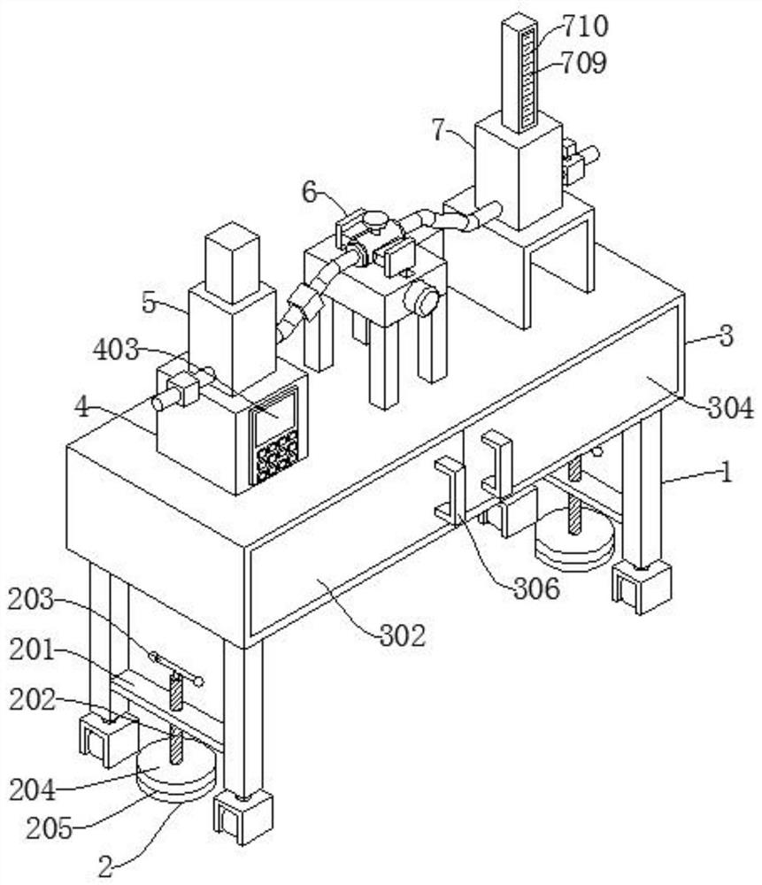
[0041] Such as figure 1 , image 3 , Figure 5 , Figure 6 , Figure 7 , Figure 8 , Figure 9 As shown, a tightness test device produced by valves for rocket engines includes a moving mechanism 1, a fixing mechanism 2, a storage mechanism 3, and a control mechanism 4. The moving mechanism 1 is equipped with a fixing mechanism 2, and the moving mechanism 1 is equipped with a The storage mechanism 3 is fixed with a control mechanism 4 above the storage mechanism 3, and also includes a booster mechanism 5, a positioning mechanism 6, and a detection mechanism 7 for increasing the air pressure in the third fixed shell 702. The booster mechanism 5 is installed on the control mechanism 4, the positioning mechanism 6 is arranged on the side of the control mechanism 4, and the detection mechanism 7 is arranged on the side of the positioning mechanism 6 away from the control mechanism 4;

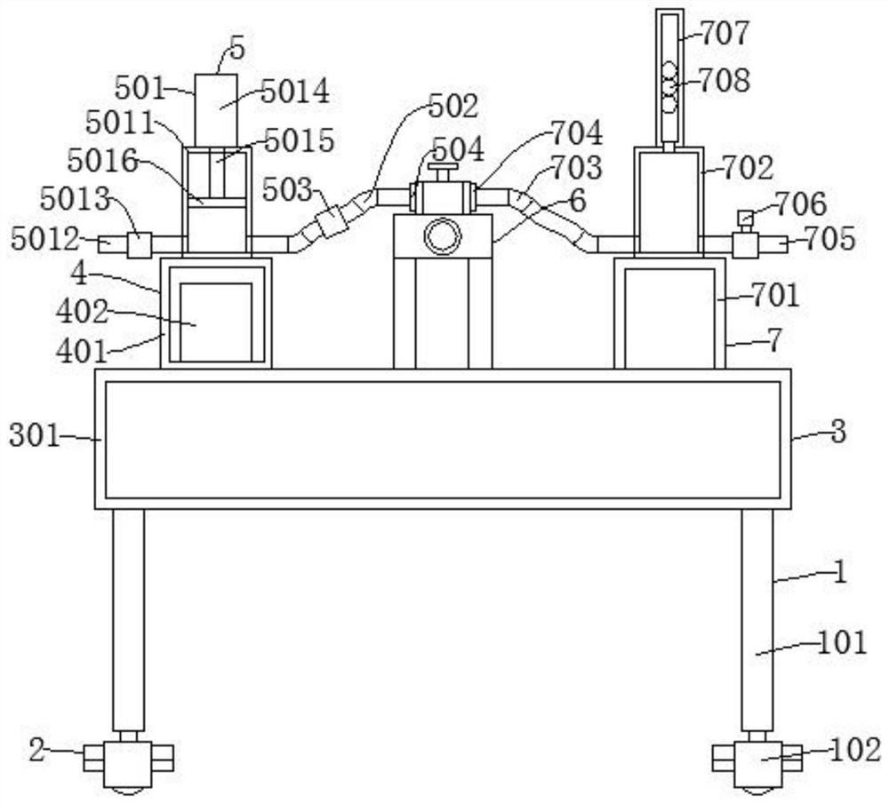
[0042] The booster mechanism 5 includes an air intake assembly 501, a first hose 502, a sec...

Embodiment 2

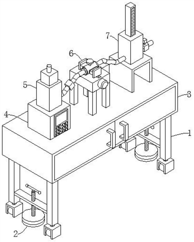
[0048] Such as figure 2 , Figure 4 , Figure 5 , Figure 6 , Figure 7 , Figure 8 , Figure 9 As shown, the difference between Embodiment 2 and Embodiment 1 is that the first fixed shell 5011, the intake pipe 5012, the first one-way valve 5013, the electric cylinder 5014, the piston rod 5015, and the piston plate 5016 are replaced by the second fixed shell 5017 , blower 5018, air pipe 5019, after the equipment is installed, start the blower 5018, and the outside air enters the second fixed shell 5017 through the air pipe 5019 under the action of the blower 5018, and the gas in the second fixed shell 5017 moves along the first The hose 502, the valve 612 and the second hose 703 enter the third fixed casing 702, the air pressure in the third fixed casing 702 increases, the plastic ball 708 in the fixed pipe 707 rises under the action of the air pressure, and the pressurization is completed Finally, close the valve 612, unload the first sealing plug 504, observe and reco...


PUM


Abstract

The invention discloses a sealing test device for rocket engine valve production, and the device comprises a moving mechanism, a fixing mechanism, a storage mechanism and a control mechanism, and is characterized in that the fixing mechanism is mounted on the moving mechanism, the storage mechanism is mounted above the moving mechanism, and the control mechanism is fixed above the storage mechanism; the device also comprises a pressurization mechanism which is used for increasing the air pressure in the third fixed shell, a positioning mechanism and a detection mechanism; the pressurization mechanism is installed above the control mechanism, the positioning mechanism is arranged on one side of the control mechanism, and the detection mechanism is arranged on the side, away from the controlmechanism, of the positioning mechanism. By arranging the pressurizing mechanism, the air pressure in the third fixing shell is increased through the air inlet assembly, the sealing performance of the valve is judged by observing the height of the plastic ball, the inspection process is simple and convenient, and cleaning is not needed.

Description

technical field [0001] The invention relates to the technical field of advanced spaceflight power design, in particular to a sealing performance test device for rocket engine valve production. Background technique [0002] A rocket engine is a jet engine that uses the principle of impulse, has its own propellant, and does not rely on external air. A rocket engine is a type of jet engine that converts the reactant (propellant) in a propellant tank or vehicle into a high-speed jet that generates thrust due to Newton's third law of motion. Rocket engines can be used for spacecraft propulsion, and can also be used for missiles to fly in the atmosphere. Most rocket engines are internal combustion engines, although non-combustion versions are also available. [0003] Valves used in rocket engines need to be tested for tightness after production. The existing test and assembly devices have the following problems that need to be solved urgently: [0004] 1. Most of the devices us...

Claims


Application Information

Patent Timeline
Patent Type & Authority Applications(China)
IPC IPC(8): G01M3/28G01M3/02B25B11/00
CPCB25B11/00G01M3/025G01M3/2876
Inventor 成广行付家豪
Owner 成广行
Why Eureka
Try Eureka