A cooling system for a combustion engine and a further object

A technology of cooling system, internal combustion engine, applied in the direction of engine cooling, liquid cooling, internal combustion piston engine, etc.

Inactive Publication Date: 2019-01-04
SCANIA CV AB
View PDF7 Cites 0 Cited by
  • Summary
  • Abstract
  • Description
  • Claims
  • Application Information

AI Technical Summary

Problems solved by technology

In this case, for example, there is a risk that coolant at too low a temperature is led to the internal combustion engine

Method used


Image

  • A cooling system for a combustion engine and a further object
  • A cooling system for a combustion engine and a further object
  • A cooling system for a combustion engine and a further object

Examples


Embodiment Construction

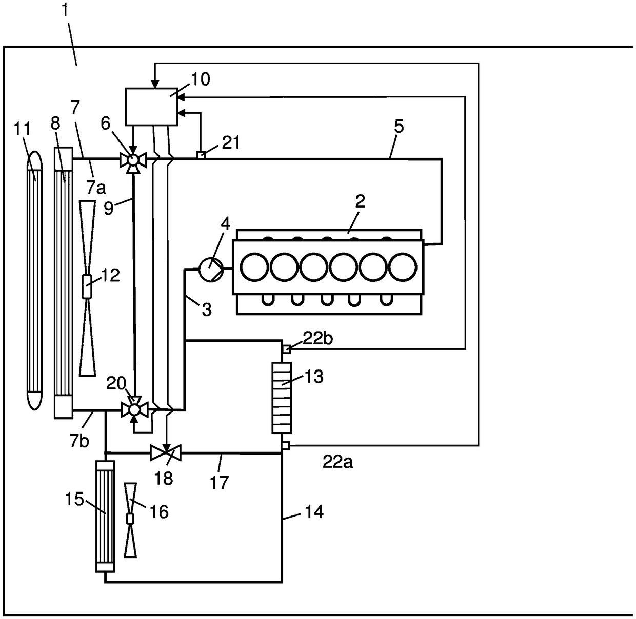
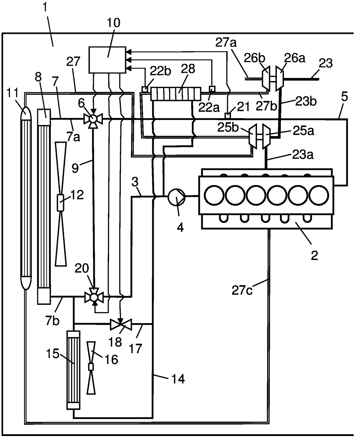
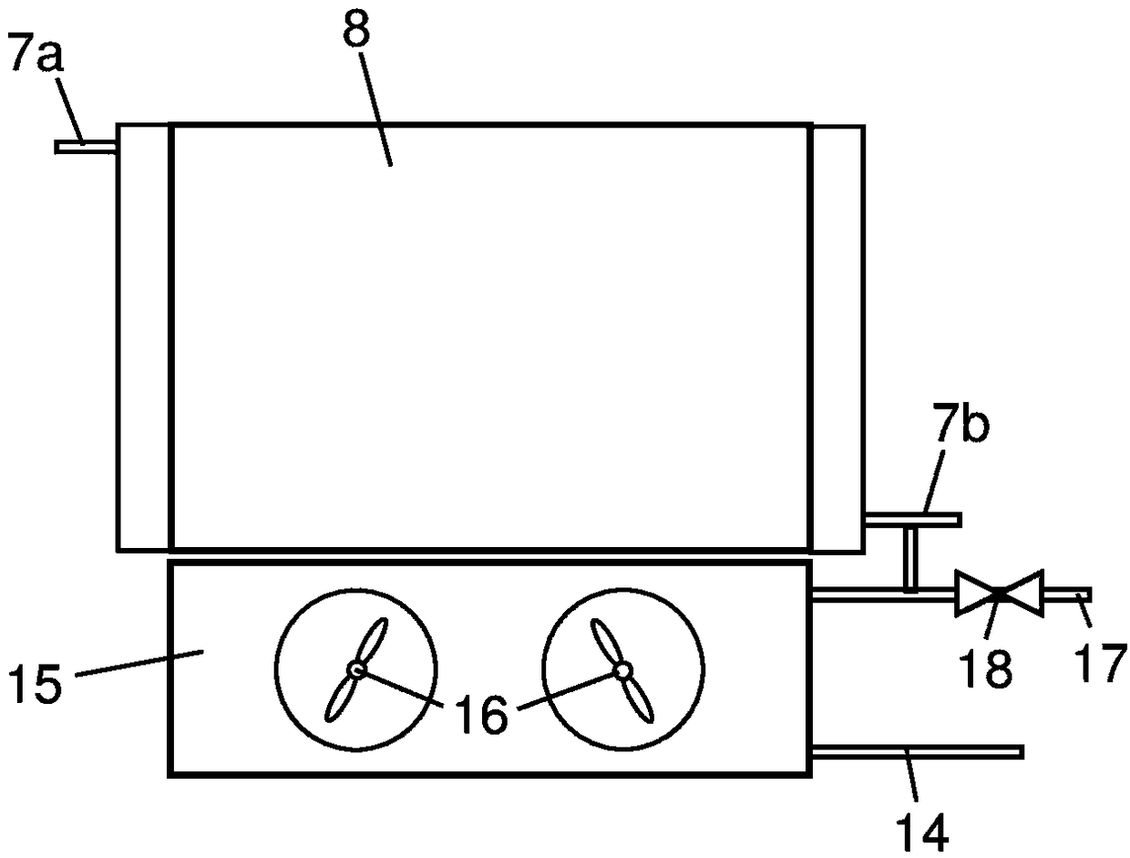
[0021] figure 1A vehicle 1 powered by an internal combustion engine 2 is schematically shown. The vehicle 1 may be a heavy vehicle and the internal combustion engine 2 may be a diesel engine. The vehicle 1 comprises a cooling system comprising an engine inlet line 3 provided with a pump 4 for circulating coolant in the cooling system. The coolant initially circulates through the internal combustion engine 2 . Coolant leaving the internal combustion engine 2 is received in the engine outlet line 5 . A first valve arrangement in the form of a first three-way valve 6 is arranged at one end of the engine outlet line 5 . The first three-way valve 6 has one inlet opening and two outlet openings. The cooling system comprises a main radiator line 7 for leading coolant through a main radiator 8 . The main radiator lines 7 include a main radiator inlet line 7a and a main radiator outlet line 7b. The cooling system includes a main radiator bypass line 9 for directing coolant around...


PUM


Abstract

The present invention relates to a cooling system configured to cool a combustion engine (2) and at least one further object (18) in a vehicle (1). The cooling system comprises a main radiator (8), amain radiator bypass line (9) directing coolant past the main radiator (8), a first valve device (6) receiving coolant from a coolant line (5) and directing it to the main radiator line (7) and the main radiator bypass line (9), an auxiliary circuit (14) directing coolant to the further object (13, 28), a main radiator outlet line (7b) directing at least a part of the coolant leaving the main radiator (8) to the auxiliary circuit (14), and a second valve device (20) receiving coolant from the main radiator (11) and / or the main radiator bypass line (9) and directing it to the auxiliary circuit(14) and / or the engine inlet line (3). The auxiliary circuit (14) comprises an auxiliary radiator (15) and an auxiliary radiator bypass line (17) directing coolant past the auxiliary radiator (15) which are arranged in an upstream position of the further object (13, 28) in the auxiliary circuit (14) and a bypass valve (18) configured to control the coolant flow through the auxiliary radiator bypass line (17).

Description

technical field [0001] The invention relates to a cooling system for internal combustion engines and further objects according to the preamble of claim 1 . Background technique [0002] Cooling systems in heavy vehicles are used many times to cool the internal combustion engine and at least one other object that requires a lower operating temperature than the internal combustion engine. Further objects may be the working medium cooled in the condenser of the WHR system, the charge air cooled in the charge air cooler, the power electronics of the hybrid vehicle, etc. In this case, at least two different coolant temperature levels need to be generated in the cooling system. Such a cooling system may be equipped with a main radiator and an auxiliary radiator that cools the coolant to a lower temperature than the main radiator. The higher temperature coolant is directed to the internal combustion engine, and the lower temperature coolant is directed to another object. During ...

Claims


Application Information

Patent Timeline
Patent Type & Authority Applications(China)
IPC IPC(8): F01P7/16F01P3/18F02B29/04
CPCF01K23/065F01K23/10F01P3/20F01P7/165F01P2003/182F02B29/0443F02G5/00Y02T10/12F01P3/18F01P2025/08F01P2060/02F01P2060/14F01P2007/146F01P2050/24
Inventor Z·卡多斯O·哈尔M·埃克曼
Owner SCANIA CV AB
Why Eureka
Try Eureka