A hydraulic clutch cooling device

A technology for hydraulic clutches and cooling devices, applied in clutches, fluid-driven clutches, non-mechanical drive clutches, etc., can solve the problems of oil pollution, unfavorable hydraulic clutch control, unfavorable protection system key components, etc., to achieve flexible installation position configuration, Promotes magazine precipitation and improves cleanliness

Active Publication Date: 2018-09-07
ZHEJIANG UNIV
View PDF6 Cites 0 Cited by
  • Summary
  • Abstract
  • Description
  • Claims
  • Application Information

AI Technical Summary

Problems solved by technology

However, on the one hand, this method cannot guarantee the oil temperature in the control circuit, which is not conducive to the control of the hydraulic clutch; on the other hand, the iron filings and other pollutants generated by the friction plate contact directly enter the oil tank, seriously polluting the oil, which is not conducive to the protection system. key components of

Method used


Image

  • A hydraulic clutch cooling device
  • A hydraulic clutch cooling device
  • A hydraulic clutch cooling device

Examples


Embodiment 1

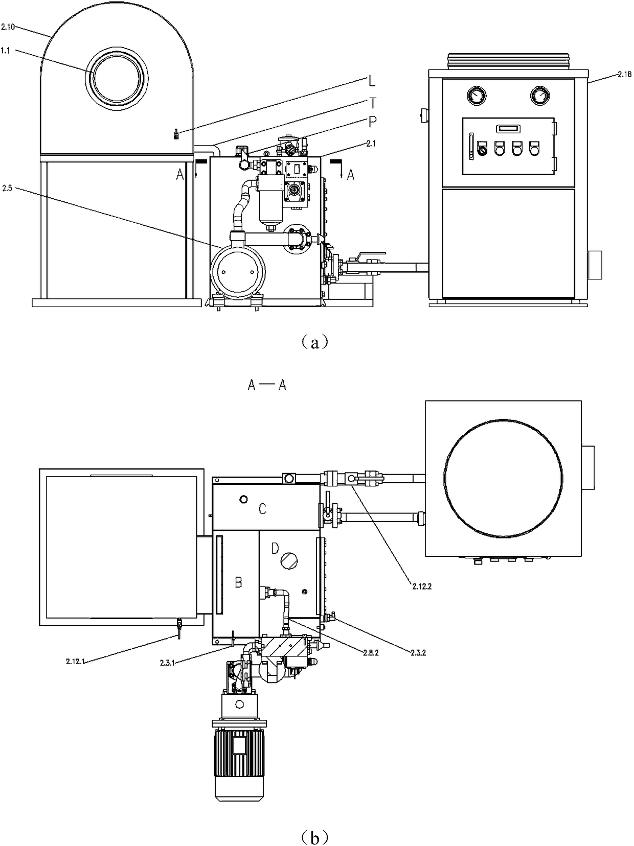
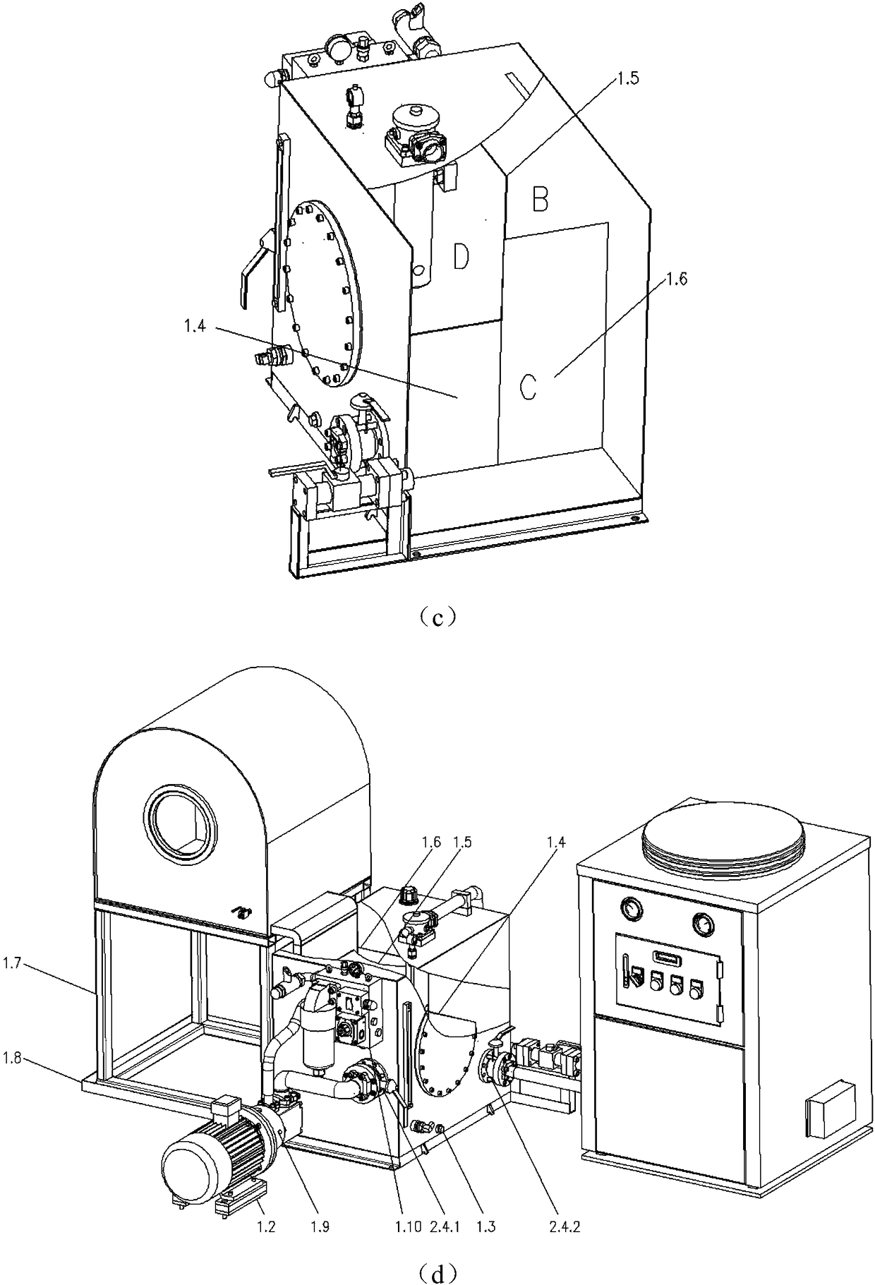
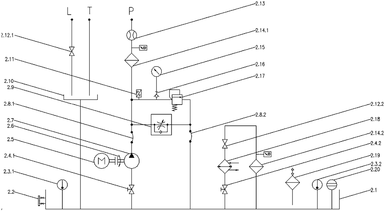
[0026] Embodiment 1: In this embodiment, the device includes a first partition 1.4, a second partition 1.5, a third partition 1.6, a first thermometer 2.3.1, a second thermometer 2.3.2 and a pressure sensor 2.11. The specific working process is as follows:

[0027] The AC motor 2.5 starts, and drives the hydraulic pump 2.7 to work through the shaft coupling 2.6. The hydraulic pump 2.7 draws oil from the oil tank 2.1 through the first butterfly valve 2.4.1, and the oil enters the valve block 1.10 through the first hose 2.8.1. The supplied oil first passes through the one-way throttle valve 2.9, and by adjusting the one-way throttle valve 2.9, the flow rate used to cool the hydraulic clutch can be adjusted to avoid excessive cooling oil pressure, and the excess oil will pass through the second The hose 2.8.2 returns to the fuel tank 2.1. The supplied cooling oil pressure is detected by a pressure sensor 2.11 and a pressure gauge 2.15 installed at the inlet of the one-way throt...


PUM


Abstract

The invention discloses a hydraulic clutch cooling device which comprises a cooling oil recovery tank, a hydraulic power unit and an oil cooler, wherein the cooling oil recovery tank comprises a cooling oil recovery cover, a sealing ring, a cutoff ball valve, a cooling oil recovery cover base and an oil sump; the hydraulic power unit comprises a shock absorption bar, an oil tank, a valve block, a liquid level and liquid temperature meter, a butterfly valve, an alternating current motor, a coupler, a hydraulic pump, a flexible pipe, a one-way throttle valve, a cutoff ball valve, a flowmeter, a filter, a pressure gauge, a pressure measurement joint, an overflow valve, an air filter, a liquid level meter and a bell jar. With the adoption of the hydraulic clutch cooling device, complete recovery of cooling oil of a clutch can be realized. The hydraulic clutch cooling device has the advantages that an oil recovery device is arranged flexibly, the recovery efficiency and the cooling efficiency are high, and the oil filtration effect is good.

Description

technical field [0001] The invention relates to the field of hydraulic clutch cooling, in particular to a hydraulic clutch cooling device. Background technique [0002] With the development of heavy machinery and heavy ships in China, the demand for high-power transmission devices and their control devices is increasing. The hydraulic clutch is an important connection device that controls the power transmission of the shaft system, and is an important safety guarantee and speed control device on the power transmission chain. Since the hydraulic clutch uses friction to transmit torque, when there is a speed difference between the two ends of the hydraulic clutch, that is, when the friction is dynamic friction, the friction of the hydraulic clutch generates a lot of heat. In order to dissipate this part of the heat in time and protect the friction plate, additional Oil is provided for heat dissipation of the friction plates. [0003] At present, the heat dissipation system f...

Claims


Application Information

Patent Timeline
Patent Type & Authority Patents(China)
IPC IPC(8): F16D25/12F15B21/04
CPCF15B21/042F16D25/123
Inventor 张军辉王迪徐兵刘代峰鲍静涵
Owner ZHEJIANG UNIV
Why Eureka
Try Eureka