A refrigeration equipment control system and control method

A technology of refrigeration equipment and control system, applied in refrigerators, refrigeration components, refrigeration and liquefaction, etc., can solve the problem of no refrigeration system control method, etc.

Active Publication Date: 2016-06-08
ENN SCI & TECH DEV
View PDF6 Cites 0 Cited by
  • Summary
  • Abstract
  • Description
  • Claims
  • Application Information

AI Technical Summary

Problems solved by technology

[0006] In the prior art, there is no other refrigeration control method except the above method to control the refrigeration effect of the refrigeration system. Therefore, there is no refrigeration system control method when throttling expansion devices other than the above two expansion valves are used for throttling and expansion.

Method used


Image

  • A refrigeration equipment control system and control method
  • A refrigeration equipment control system and control method
  • A refrigeration equipment control system and control method

Examples


Embodiment 1

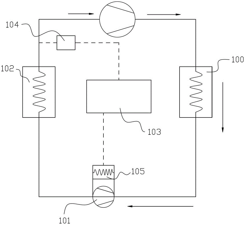
[0050] Such as figure 1 As shown, a refrigeration equipment control system described in this embodiment includes:

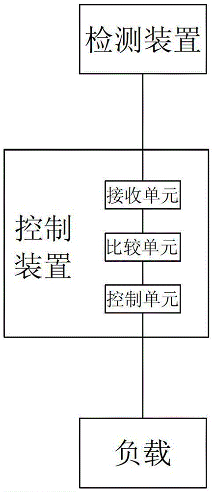
[0051] The control device 103 is connected to the load 105 and connected to the detection device 104 through communication, and is used for receiving the detection result of the detection device 104 and adjusting the load 105 according to the detection result.

[0052] The detection device 104 is arranged in the working circuit of the refrigeration system, and is used to detect the degree of superheat of the evaporator 102 , and communicates with the control device 103 to send the detection result to the control device 103 .

[0053] The throttling expansion device 101 is arranged between the condenser 100 and the evaporator 102, and includes a rotor driven by refrigerant and a stator coil arranged outside the rotor. When the rotor rotates, an induced current is generated in the stator coil, and the rotational speed of the rotor is determined by the stator coil. ...

Embodiment 2

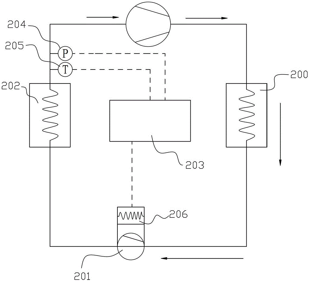
[0056] Such as Figure 2-4 As shown, a refrigeration equipment control system described in this embodiment includes:

[0057]The control device 203 is connected to the load 206 and connected to the detection device through communication, for receiving the detection result of the detection device, and adjusting the load 206 according to the detection result;

[0058] The detection device is arranged in the working circuit of the refrigeration system, and is used to detect the degree of superheat of the evaporator 202, and communicate with the control device 203, and send the detection result to the control device 203;

[0059] The throttling expansion device 201 is arranged between the condenser 200 and the evaporator 202, and includes a rotor driven by refrigerant and a stator coil arranged outside the rotor. When the rotor rotates, an induced current is generated in the stator coil, and the rotational speed of the rotor is determined by the stator coil. Influenced by the cha...

Embodiment 3

[0087] Embodiment three, such as Figure 5 As shown, the difference between the present embodiment and the second embodiment is that the detection device adopted in the third embodiment is composed of three temperature sensors 304, and the three temperature sensors 304 are respectively arranged at the outlet of the condenser 300 and at the end of the evaporator 302. At the inlet and the outlet of the evaporator 302, the control device 303 obtains the degree of superheat of the evaporator 302 through the temperature signals detected by the three temperature sensors 304, compares it with the set degree of superheat, and controls the load 305 according to the comparison result.

[0088] At the same time, in this embodiment, the load 305 adopts an energy recovery device, which is arranged between the condenser 300 and the throttling expansion device 301. The energy recovery device consumes the electric energy provided by the throttling expansion device 301. For example, the load 30...


PUM


Abstract

The invention discloses a refrigerating device control system which comprises a control device, a detecting device, a throttling expansion device and a load. The control device is connected with the load and in communication connection with the detecting device and used for receiving a detecting result of the detecting device and adjusting the load based on the detecting result. The detecting device is arranged in a work circuit of a refrigerating system and used for detecting the degree of superheat of an evaporator, is in communication connection with the control device and transmits the detecting result to the control device. The throttling expansion device is arranged between a condenser and the evaporator and comprises a rotor which is driven by a refrigerating agent and a stator coil arranged outside the rotor. When the rotor rotates, induced currents are generated in the stator coil. A rotation speed of the rotor is affected by variation of currents in the stator coil. The load is arranged at the induced current output end of the throttling expansion device and consumes the induced currents to operate. The involved load is adjusted by the control device so as to adjust the induced currents in the stator coil. The flow of the refrigerating agent is changed and the refrigerating effect of the refrigerating device is adjusted.

Description

technical field [0001] The invention relates to a refrigeration system, in particular to a refrigeration equipment control system and control method. Background technique [0002] The commonly used refrigeration device includes a circulation circuit composed of a compressor, a condenser, a throttling expansion device and an evaporator that are fluidly connected in sequence. The refrigerant undergoes compression, condensation, throttling expansion, evaporation, etc. cycle. In the refrigeration process, the refrigerant is first adiabatically compressed into high-pressure steam in the compressor, then condensed into a high-pressure normal temperature liquid in the condenser, expands through the throttle valve, absorbs heat in the evaporator and evaporates into steam, and then returns to the compressor. The more refrigerant that flows per unit time in the circulation loop, the more cooling capacity is provided, and the cooling effect of the refrigeration system is better. On th...

Claims


Application Information

Patent Timeline
Patent Type & Authority Patents(China)
IPC IPC(8): F25B49/02
Inventor 陈亚霖李文乐刘长青李伟仵浩甘中学
Owner ENN SCI & TECH DEV
Why Eureka
Try Eureka