
Laser marking control method and device, computer equipment and storage medium

A laser marking and control method technology, applied in laser welding equipment, welding equipment, metal processing equipment, etc., can solve the problems of speed up, laser marking takes a long time, lens inertia can not be accurately positioned, etc., to achieve the elimination of communication delay , shorten time-consuming and improve efficiency

Active Publication Date: 2019-01-11
CHANGZHOU INNO MACHINING +1
View PDF12 Cites 5 Cited by
  • Summary
  • Abstract
  • Description
  • Claims
  • Application Information

AI Technical Summary

Problems solved by technology

However, both of these two traditional methods cannot be accurately positioned due to the inertia of the lens after the high-speed movement of the galvanometer, and can only be waited by increasing the overshoot delay, which cannot be accelerated, resulting in long laser marking. , the efficiency of laser marking can not be effectively improved

Method used


Image

  • Laser marking control method and device, computer equipment and storage medium
  • Laser marking control method and device, computer equipment and storage medium
  • Laser marking control method and device, computer equipment and storage medium

Examples


Embodiment Construction

[0045] In order to make the purpose, technical solution and advantages of the present application clearer, the present application will be further described in detail below in conjunction with the accompanying drawings and embodiments. It should be understood that the specific embodiments described here are only used to explain the present application, and are not intended to limit the present application.

[0046] It can be understood that the terms "first", "second" and the like used in this application may be used to describe various elements herein, but these elements are not limited by these terms. These terms are only used to distinguish one element from another element. For example, a first parsing module could be termed a second parsing module, and, similarly, a second parsing module could be termed a first parsing module, without departing from the scope of the present application. Both the first analysis module and the second analysis module are analysis modules, bu...


PUM


Abstract

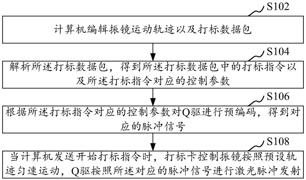
The invention relates to a laser marking control method and device, computer equipment and a storage medium. The method comprises the steps that a computer edits a galvanometer movement trajectory anda marking data package; the marking data package is analyzed, marking instructions in the marking data package and control parameters corresponding to the marking instructions are obtained; accordingto the control parameters corresponding to the marking instructions, a Q drive is precoded, and corresponding pulse signals are obtained; when the computer sends marking start instructions, a markingcard controls a galvanometer to move at a constant speed according to the preset trajectory, and the Q drive caries out laser pulse emission according to the corresponding pulse signals. Since the galvanometer is controlled to move for scanning, and the Q drive is precoded in advance, when the galvanometer moves to a point where marking is needed, preset pulse is sent, overshoot delay of the galvanometer is omitted, communication delay of the marking card and a laser device is also omitted, laser marking time consumption is shortened, and laser marking efficiency is improved.

Description

technical field [0001] The invention relates to the technical field of laser processing, in particular to a laser marking control method, device, computer equipment and storage medium. Background technique [0002] At present, with the development of laser processing technology, the application fields of laser processing technology are becoming more and more extensive. Among them, laser marking technology is one of the largest application fields of laser processing. Laser marking is a marking method that uses a high-energy-density laser to locally irradiate the workpiece to vaporize the surface material or undergo a chemical reaction of color change, thereby leaving a permanent mark. Laser marking can print various characters, symbols and patterns, etc., and the character size can range from millimeters to microns, which has special significance for product anti-counterfeiting. [0003] At present, laser marking has experienced the development of mask marking, array markin...

Claims


Application Information

Patent Timeline
IPC IPC(8): B23K26/362B23K26/70
CPCB23K26/362B23K26/361B23K26/702
Inventor 韩世华
Owner CHANGZHOU INNO MACHINING
Learn More