Air outlet device and air conditioner indoor unit
An indoor unit and air outlet technology of an air conditioner, which is applied to air conditioning systems, lighting and heating equipment, space heating and ventilation, etc., can solve the problems of small air supply range, large diffusion angle, and small diffusion angle, etc. To achieve the effect of increasing the air supply angle and air supply range, large air supply angle and air supply range, and improving the comfort of use
- Summary
- Abstract
- Description
- Claims
- Application Information
AI Technical Summary
Problems solved by technology
Method used
Image
Examples
Embodiment 1
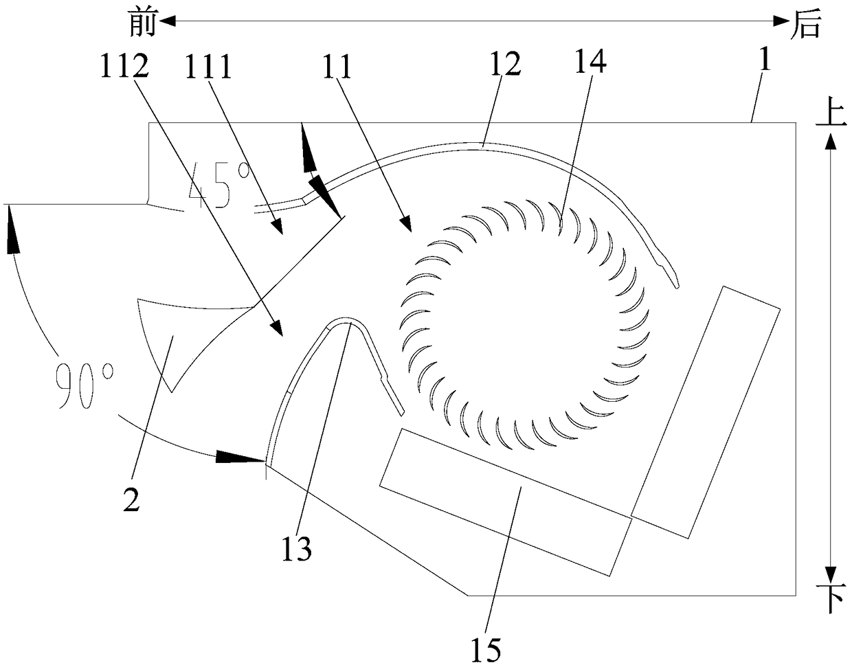
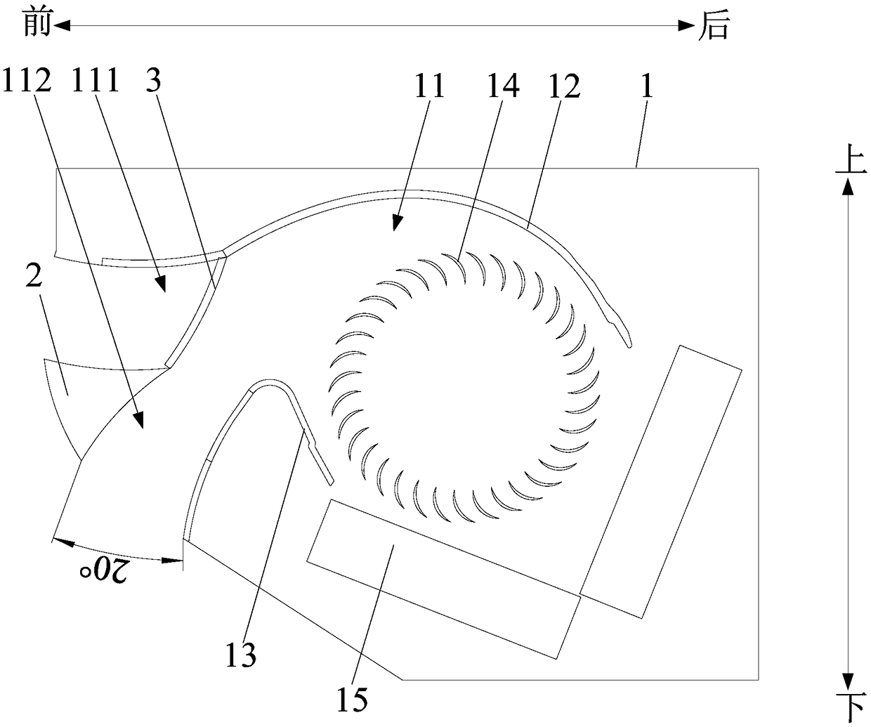
[0036] Such as Figure 1 to Figure 3 As shown, the present invention provides an air outlet device, including an air guide block 2 and a baffle plate 3, one end of the air duct 11 is an air outlet, and the air guide block 2 is arranged at the air outlet to displace the air outlet. The air channel 11 at the air outlet is divided into a first air channel 111 and a second air channel 112 , and the baffle plate 3 is used to block the first air channel 111 and / or the second air channel 112 . Wherein the air outlet in the present application is provided on the front side of the indoor unit of the air conditioner. Taking the indoor unit of the air conditioner fixed on the wall as an example, the side of the indoor unit of the air conditioner fixed on the wall is the rear side. side, the side of the indoor unit of the air conditioner away from the wall is the front side; Figure 1 to Figure 3 As shown, the air outlet is located on the front side of the indoor unit of the air conditio...
Embodiment 2
[0051] The technical solution of this embodiment is substantially the same as that of Embodiment 1, the main difference is that the baffle plate 3 is provided in the first air flow channel 111 and the second air flow channel 112 in this embodiment; optionally , the baffle 3 includes a first baffle and a second baffle, the first baffle is arranged in the first airflow passage 111; the second baffle is arranged in the second airflow passage 112 . Preferably, the first baffle is hinged to the upper wall of the air duct 11 or the air guide block 2 to open or close the first airflow channel 111 , and the second baffle is connected to the air duct 11 The lower wall surface or the air guide block 2 are hinged to open or close the second airflow channel.
[0052] According to an example of the present application, one end of the first baffle is hinged to the inner wall on one side of the air duct 11, specifically, one end of the first baffle is hinged to the upper wall of the air duc...
Embodiment 3
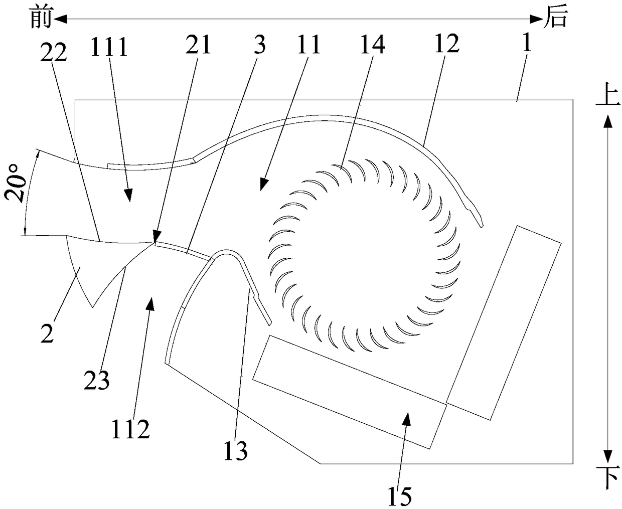
[0060] This embodiment is substantially the same as the technical solutions in Embodiment 1 and Embodiment 2. The main difference is that, as Figure 4 As shown, in this embodiment, the baffle 3 is connected to the outer end of the air guide block 2, that is, the baffle 3 is located at the opposite end of the air guide block 2 in the air duct 11; Such as image 3 As shown, the air guide block 2 is triangular in shape, and a tip of the triangular-shaped air guide block 2 extends into the air duct 11, and the side corresponding to the tip is located outside the air duct 11; preferably The first air flow channel 111 is formed between one side forming the tip and the inner wall on one side of the air duct 11, and the other side forming the tip and the inner wall on the other side of the air duct 11 Form the second air flow channel 112; wherein the tip extending into the air channel 11 is the first end 21, and the two sides constituting the first end 21 are the first side 22 and t...
PUM
 Abstract
Description
Claims
Application Information
 - R&D
- Intellectual Property
- Life Sciences
- Materials
- Tech Scout
- Unparalleled Data Quality
- Higher Quality Content
- 60% Fewer Hallucinations
Browse by: Latest US Patents, China's latest patents, Technical Efficacy Thesaurus, Application Domain, Technology Topic, Popular Technical Reports.
© 2025 PatSnap. All rights reserved.Legal|Privacy policy|Modern Slavery Act Transparency Statement|Sitemap|About US| Contact US: help@patsnap.com


