An anti-retrograde deceleration belt
A technology of speed bumps and the other side, which is applied in the field of anti-reverse speed bumps, can solve the problems of motor vehicle safety hazards, collisions, motor vehicle scratches, etc., and achieve the effect of flexible and adjustable height and inclination angle
- Summary
- Abstract
- Description
- Claims
- Application Information
AI Technical Summary
Problems solved by technology
Method used
Image
Examples
Embodiment 1
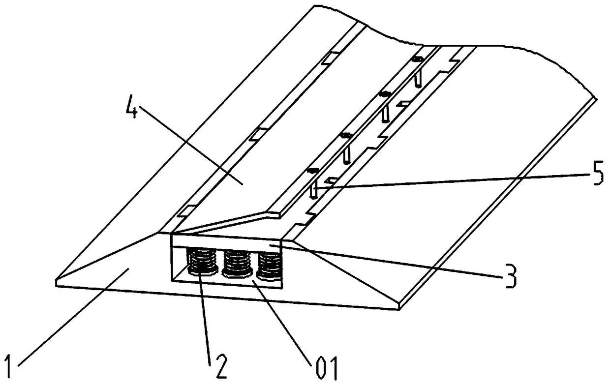
[0025] A kind of anti-reverse speed reduction belt of this embodiment, such as figure 1 As shown, it includes an installation base 1, a deceleration seat 3, and a one-way plate 4. It is characterized in that, the middle part of the installation base 1 is provided with a through groove 01 perpendicular to the driving direction, and the vertical sliding installation in the through groove 01 is The deceleration seat 3, a number of elastic parts 2 are connected between the bottom of the deceleration seat 3 and the bottom of the through groove 01; the one-way plate 4 is in the shape of an inclined slope, and the bottom end of the one-way plate 4 is in the shape of a deceleration One side of the seat 3 is hinged, and the top end of the inclined plane of the one-way plate 4 is connected with the other side of the deceleration seat 3 through an adjusting bolt 5 .
[0026] First install the installation base 1 on the road surface with bolts, and then install the deceleration seat 3 int...
Embodiment 2
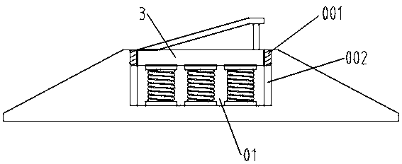
[0028] This embodiment is further optimized on the basis of embodiment 1, such as figure 2 As shown, a number of vertical sliding slots 001 are provided on the side wall of the slot 01 of the installation base 1 along the direction of the slot 01 , and sliders 002 are provided on both sides of the deceleration seat 3 corresponding to the slots 001 .
[0029] Through the cooperation of the sliding groove 001 and the sliding block 002, the deceleration seat 3 can slide vertically in the through groove 01 of the installation base 1 along the sliding groove 001.
[0030] Other parts of this embodiment are the same as those of Embodiment 1, so details are not repeated here.
Embodiment 3
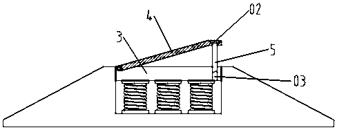
[0032] This embodiment is further optimized on the basis of above-mentioned embodiment 1 or 2, such as image 3 As shown, the top of the slope of the one-way plate 4 is provided with a via hole 02, and the other side of the deceleration seat 3 is provided with a threaded hole 03 corresponding to the via hole 02, and the via hole 02 and the threaded hole 03 are inserted with Adjustment bolt 5.
[0033] An adjusting bolt 5 is inserted in the through hole and the threaded hole. According to the actual road conditions and the size of the wheel diameter of the passing vehicle, when the height and angle of the one-way plate 4 need to be adjusted, the adjusting bolt 5 only needs to be rotated to make the adjustment bolt 5 The height change can realize the change of the height of the one-way plate 4. When the height of the one-way plate 4 changes, the one-way plate 4 will rotate a certain angle around the hinge with the deceleration seat 3, so as to realize the height of the one-way p...
PUM
 Abstract
Description
Claims
Application Information
 - R&D
- Intellectual Property
- Life Sciences
- Materials
- Tech Scout
- Unparalleled Data Quality
- Higher Quality Content
- 60% Fewer Hallucinations
Browse by: Latest US Patents, China's latest patents, Technical Efficacy Thesaurus, Application Domain, Technology Topic, Popular Technical Reports.
© 2025 PatSnap. All rights reserved.Legal|Privacy policy|Modern Slavery Act Transparency Statement|Sitemap|About US| Contact US: help@patsnap.com


