Plate-type sliding layer support and construction method thereof

A plate type, sliding layer technology, applied in bridge parts, erection/assembly of bridges, bridge materials, etc., can solve the problems of limited service life of bearing maintenance plans, unfavorable railway safety operation, inconsistent roller shaft inclinations, etc., to reduce later maintenance. Maintenance cost, wide applicability, good support effect

Pending Publication Date: 2020-08-04
中铁桥隧技术有限公司 +1
View PDF0 Cites 2 Cited by
  • Summary
  • Abstract
  • Description
  • Claims
  • Application Information

AI Technical Summary

Problems solved by technology

[0006] 1) The bolts of some roller shaft connecting plates are cut off;
[0007] 2) The inclination angle of the roller shaft is inconsistent, the inclination angle of the roller shaft deformed by the connecting bolt is larger than that of the other roller shafts, and the inclination of the roller shaft cut off by the bolt is serious
[0012] Disadvantages of the original plan: Due to the characteristics of the old shaft support, the bolts on the connecting plate will still break after the support is repaired. After replacing the old shaft with a new shaft, the inclination of the shaft will gradually decrease with the rotation of the support and the longitudinal movement. Inconsistent, in short, the service life of the original support maintenance plan is limited, and the maintenance frequency is relatively frequent, which is not conducive to the safe operation of the railway

Method used


Image

  • Plate-type sliding layer support and construction method thereof
  • Plate-type sliding layer support and construction method thereof
  • Plate-type sliding layer support and construction method thereof

Examples


Embodiment Construction

[0043] The present invention will be specifically introduced below in conjunction with the accompanying drawings and specific embodiments.

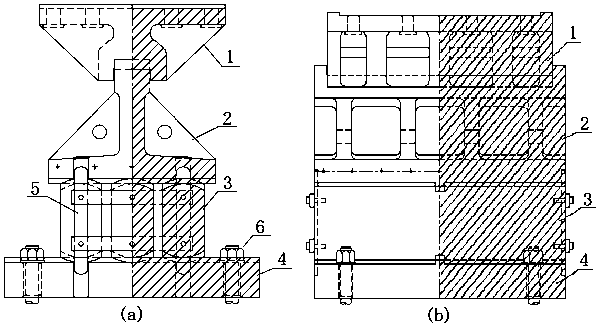
[0044] The utility model relates to a plate-type sliding layer bearing, which comprises an upper swing structure, a middle sliding layer structure and a base 4. The swing structure is composed of matching upper swing 1 and lower swing 2 (following the swing structure of the original roller bearing), and the swing direction is along the bridge;

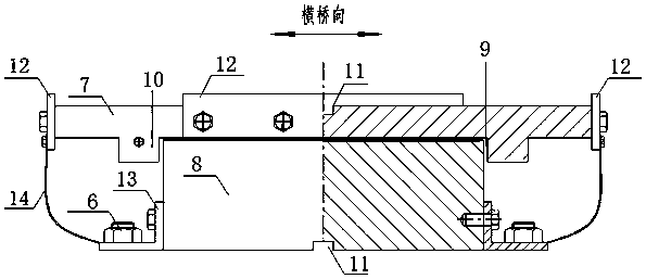
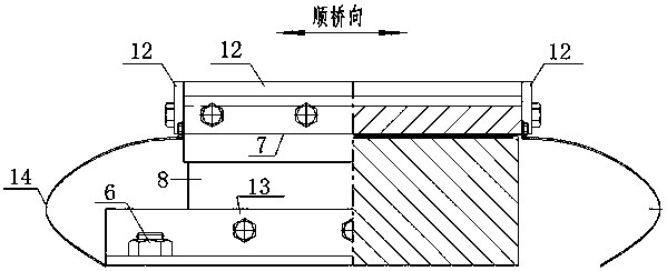
[0045] The sliding layer structure is composed of matching upper bearing plate 7 and lower bearing plate 8; the upper bearing plate 7 is plate-shaped, the top surface and the bottom surface are both flat, and the top surface is provided with a limit card that matches the limit beam on the bottom surface of the hem 2 The groove 11 is provided with a pair of crossbeams 10 on the bottom surface, and the chute 9 matching the top of the lower bearing plate 8 is formed between the crossbeams 10, and the...


PUM


Abstract

The invention discloses a plate-type sliding layer support which comprises a swing structure on the upper portion, a sliding layer structure in the middle and a base. The swing structure comprises anupper swing and a lower swing which are matched, and the swing direction is along the bridge direction. The sliding layer structure comprises an upper bearing plate and a lower bearing plate which arematched, and the sliding direction is the bridge direction. A sliding groove matching the top face of the lower bearing plate is formed in the bottom face of the upper bearing plate in the bridge direction, a limiting clamping groove matching the limiting beam on the bottom face of the lower swing is formed in the top face of the upper bearing plate, and a limiting clamping groove matching the limiting beam on the top face of the base is formed in the bottom face of the lower bearing plate. A roller shaft in a roller shaft movable support is replaced with the sliding layer structure, the longitudinal sliding function of an original support is achieved, an original swing structure is reserved, the cost is saved, the renewal difficulty is lowered, and the renewal efficiency is improved. Thedefects that a roller shaft connecting bolt of the original roller shaft support is easy to cut off and the inclination angles of the roller shafts are inconsistent are overcome; and the service lifeof the support is prolonged, safe operation of a railway is ensured, and high practicability and wide applicability are achieved.

Description

technical field [0001] The invention relates to a bearing, in particular to a plate type sliding layer bearing, which belongs to the technical field of railway bridge bearings. Background technique [0002] Bridge bearings are important structural components connecting the bridge superstructure and substructure. It can reliably transmit the reaction force and deformation (displacement and rotation angle) of the bridge superstructure to the bridge substructure, so that the actual stress of the structure is consistent with the calculated theoretical diagram. [0003] During the use of railway bridges, compared with road bridges, they are subject to higher frequency vibrations; therefore, a large number of existing technologies such as figure 1 The roller shaft support shown (figure a is in the direction of the bridge, and figure b is in the direction of the bridge) is the main support structure. [0004] The roller bearing is mainly composed of main components such as the ba...

Claims


Application Information

Patent Timeline
IPC IPC(8): E01D19/04E01D22/00E01D101/30
CPCE01D19/048E01D22/00E01D2101/30
Inventor 刘华肖啸徐伟张宗辉胡晓红崔海彭伟林
Owner 中铁桥隧技术有限公司
Why Eureka
Try Eureka