
Passive pay-off rack

A pay-off stand, passive technology, applied in the direction of conveying filamentous materials, thin material handling, transportation and packaging, etc., can solve the problems of unstable pay-off, inconvenient tension adjustment, etc., to achieve reasonable collocation, equipment cost saving, The effect of ensuring orderliness

Pending Publication Date: 2019-01-18
安徽光纤光缆传输技术研究所
View PDF9 Cites 2 Cited by
  • Summary
  • Abstract
  • Description
  • Claims
  • Application Information

AI Technical Summary

Problems solved by technology

[0003] A passive pay-off stand proposed by the invention can solve the technical problems of inconvenient tension adjustment and unstable pay-off of the traditional passive pay-off stand

Method used


Image

  • Passive pay-off rack
  • Passive pay-off rack

Examples


Embodiment Construction

[0026] In order to make the purpose, technical solutions and advantages of the embodiments of the present invention clearer, the technical solutions in the embodiments of the present invention will be clearly and completely described below in conjunction with the drawings in the embodiments of the present invention. Obviously, the described embodiments It is a part of embodiments of the present invention, but not all embodiments.

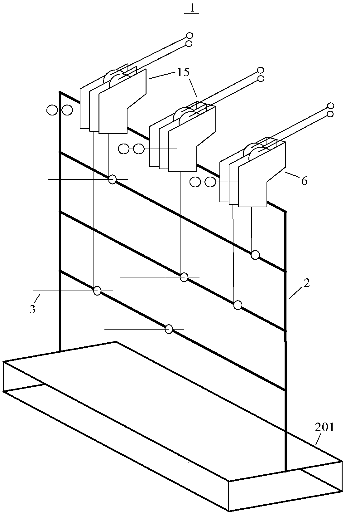
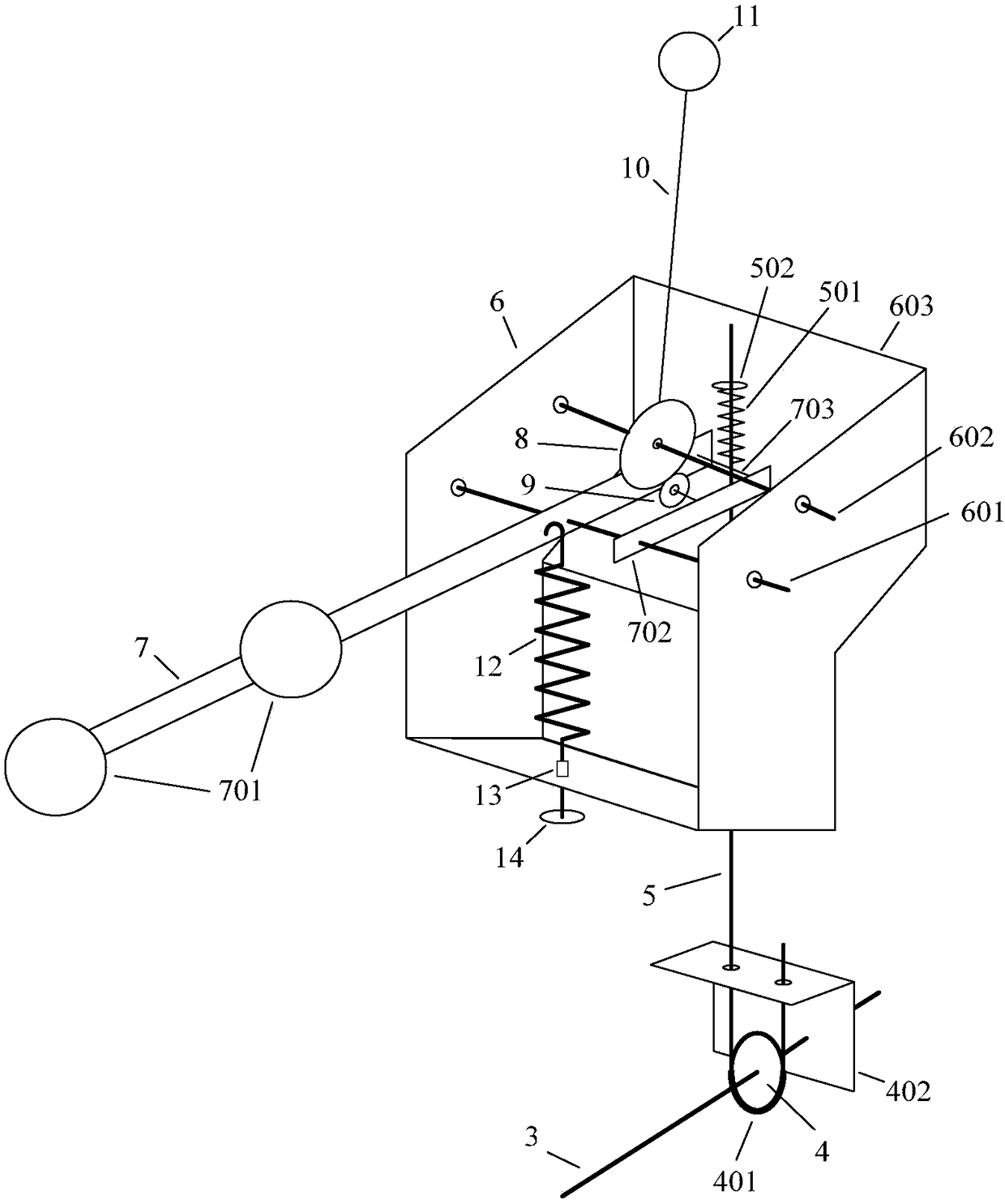
[0027] Such as figure 1 with figure 2 As shown, a passive pay-off stand provided by the embodiment of the present invention includes a pay-off stand main body 1, on which a bearing frame 2, a pay-off shaft 3 and a tension adjustment group 15 are arranged; The base 201 is fixedly installed at the bottom of the frame 2, and four bearing rods are installed horizontally on the inner side of the carrier frame 2, numbered from top to bottom as the No. 1 load rod, the No. 2 load rod, the No. Rod; the tension adjustment group 15 is arranged on the top of...


PUM


Abstract

The invention relates to a passive pay-off rack. The technical problem that for a traditional passive pay-off rack, tension adjustment is inconvenient, and paying off is unstable can be solved. The passive pay-off rack comprises a pay-off rack main body which comprises a bearing frame, a bearing rod and a tension adapter, and a pay-off shaft is arranged under the tension adapter; the tension adapter comprises a transversely arranged threading plate and a longitudinally arranged swing rod, a cycloid gear is arranged on the top of the swing rod, the bottom of the swing rod is fixed to an elliptic bearing which is fixed in a shell, a circular bearing is fixed to the threading plate, the elliptic bearing and the circular bearing are tangently arranged, and the elliptic bearing is arranged above the circular bearing; the passive pay-off rack further comprises a vertical screw rod which is fixedly connected with the threading plate, the bottom of the vertical screw rod is fixedly connected with one end of a brake strap, the other end of the brake strap is fixed to the bearing rod, and a brake wheel is arranged on the upper portion of the brake strap and connected with the pay-off shaft.The passive pay-off rack is firm in structure, very small in abrasion loss and stable in pay-off tension.

Description

technical field [0001] The invention relates to the technical field of cable processing equipment, in particular to a passive pay-off frame. Background technique [0002] In the production process of some optical cables and cables, pay-off racks are required. There are two main types of pay-off racks: active pay-off and passive pay-off. Among them, active pay-off is mainly used for more precise requirements on pay-off tension. In occasions, passive pay-off is used in occasions where the precision of pay-off tension is not high. Since the active pay-off requires the use of electrical components such as motors and controllers, the price of the active pay-off unit is higher than that of the passive pay-off unit under the same operating conditions. In other words, the active pay-off method is not the best choice. However, the traditional passive pay-off stand is inconvenient or difficult to adjust the pay-off tension, resulting in unstable pay-off. Contents of the invention ...

Claims


Application Information

Patent Timeline
Patent Type & Authority Applications(China)
IPC IPC(8): B65H59/10B65H59/40
CPCB65H59/10B65H59/40
Inventor 张贵生陶景升
Owner 安徽光纤光缆传输技术研究所
Learn More