Device of using implant anchorage to distalize maxillary molar

A technology of remote displacement and implantation nails, which is applied in dental implantation, dentistry, dental prosthesis, etc., can solve the problems of difficult traction force, inconvenient stainless steel wire, and difficult implantation of implants, etc., and achieves easy operation and safety. High, firm mucosal effect

Pending Publication Date: 2019-03-01
上海市口腔病防治院
View PDF0 Cites 1 Cited by
  • Summary
  • Abstract
  • Description
  • Claims
  • Application Information

AI Technical Summary

Problems solved by technology

There are currently two buccal implant anchorage methods. Method 1: If the implant is placed between the buccal first molar and the second premolar, and the first molar is pushed to the distance indirectly, the main arch wire on the labial side must be stainless steel wire. And there are second premolars that need to be removed and then moved far away, which is easy to lose anchorage
Method 2: Implants can be placed on the zygomatic alveolar ridge. The position is high and difficult, and the main

Method used


Image

  • Device of using implant anchorage to distalize maxillary molar
  • Device of using implant anchorage to distalize maxillary molar
  • Device of using implant anchorage to distalize maxillary molar

Examples


Embodiment 1

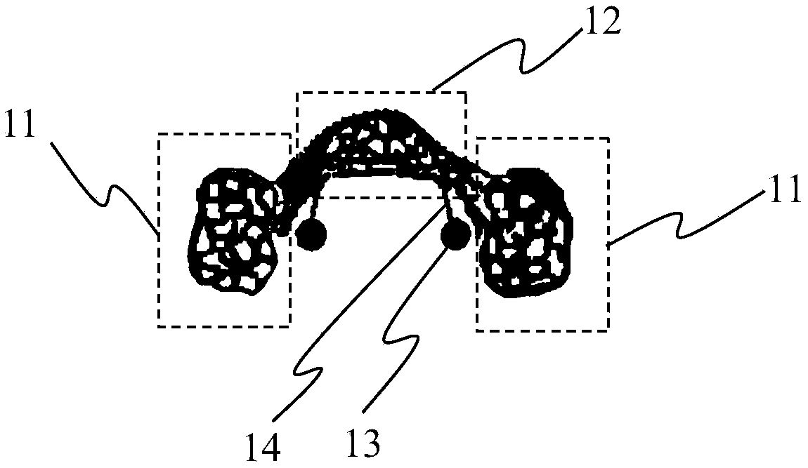
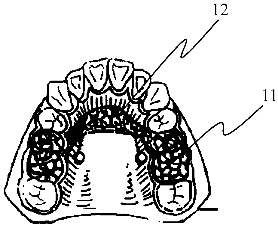
[0027] Such as figure 1 As shown, the device for using the implant anchorage to move the maxillary molars away includes: a cast bracket with a fixed part 11 on both sides of the tooth surface and a palatal connector 12 arranged between the two fixed parts on the tooth surface; an implant anchorage 13 ; The traction hook 14 and the hook of the palatal connector.

[0028] The casting bracket has two tooth surface fixing parts 11 and a palatal connecting body 12 arranged between the two tooth surface fixing parts 11 . In the initial state, the curvature of the palatal connecting body 12 is forward and fits the palatal mucosa. The area of ​​the tooth surface fixing portion 11 can cover the occlusal surfaces of two or more posterior teeth.

[0029] Implant anchorage 13, fixed on the upper jaw. The nail head of the implant anchorage 13 is flush with the furcation of the maxillary molars. In the specific operation, the position of the nail head is usually based on empirical value...

Embodiment 2

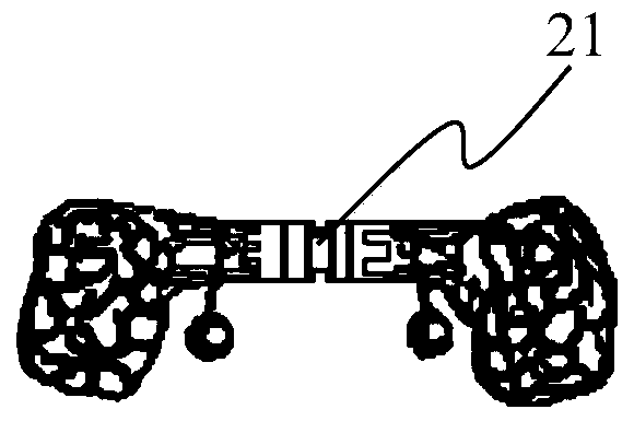
[0034] The overall structure of the device for moving maxillary molars away using implant anchorage in this embodiment is the same as that in Embodiment 1. The difference is that a helical expander is placed in the middle of the palatal connector. details as follows:

[0035] The spiral expander 21, the palatal connector has two left and right sub-palatal connectors, and the helical expander is arranged between the two sub-palatal connectors. Due to the presence of the spiral expander 21, the palatal connector is divided into two sub-palatal connectors 22 on the left and right.

[0036] When it is necessary to move the molars more than 2mm distally, because the upper posterior teeth on both sides extend backward and outward in a "eight" shape, a spiral arch expansion device 21 (Screw arch expansion device) is added at the connection part to expand the arch to both sides Cooperate with the long-distance molar push and move away, so that the molars are always moved away from t...


PUM


Abstract

The invention provides a device of using an implant anchorage to distalize a maxillary molar. The device is characterized by comprising: a cast support having palatal side connectors arranged on two lateral face fixing portions and between two face fixing portions; the implant anchorage fixed to the mandible; a palatal side connector traction hook having elasticity, wherein one end of the palatalside connector traction hook is connected with the implant anchorage, the other end of the palatal side connector traction hook is hung to the palatal side connectors, the palatal side connector traction hook applies elastic force to the palatal side connectors. The cast support covers the occlusal faces of the molars on two sides; the cast support can cover more than the occlusal faces of more than two molars, forming a plane, and ensuring that oblique movement is avoided to maximum extent during molar distalization.

Description

technical field [0001] The invention relates to a device for distantly moving maxillary molars by using implant anchorage, which belongs to dental medical equipment. Background technique [0002] Distal movement of maxillary molars is a common method for clinically solving Angle’s class II malocclusion and odontogenic crowding cases. At present, clinical methods for distal molar movement include: external force devices such as extraoral arches, J hooks, etc., which can provide strong support Intraoral force devices such as pendulum appliances, vertical screw-type push molars and movable appliances, etc., do not require high patient compliance, but they are likely to cause loss of anchorage of premolars and incisors , can not provide absolute strong anchorage, can not be corrected with labial side bonded brackets at the same time, and can only move the premolars and anterior teeth away after the molars are pushed successfully. The anchorage is easy to lose again, which is tim...

Claims


Application Information

Patent Timeline
IPC IPC(8): A61C8/00
CPCA61C8/0027A61C8/0033A61C8/0083
Inventor 潘杰刘月华
Owner 上海市口腔病防治院
Why Eureka
Try Eureka