A construction method of a flexible anchor rod

A construction method and bolt technology, which are applied in the installation of bolts, earthwork drilling, mining equipment, etc., can solve problems such as the inability to reinforce the anchor cable anchorage area, the inability to meet the geological environment, and the inability to apply pre-tightening force, etc., to achieve improved anchorage The speed of pole support, the realization of quality standardization, and the effect of efficient installation speed

Active Publication Date: 2019-09-03
CHINA UNIV OF MINING & TECH
View PDF7 Cites 0 Cited by
  • Summary
  • Abstract
  • Description
  • Claims
  • Application Information

AI Technical Summary

Problems solved by technology

However, due to the limitation of the height of the roadway, the length of the bolt can only be maintained at about 2m, and the thickness of the anchorage area of ​​the bolt can only be 2m, which is not suitable for the complex geological conditions of the current roadway, and the existing method of using the bolt cannot meet the current requirements. There are geological environment requirements
Although the common anchor cable is long enough, the installation process of the anchor cable is relatively complicated, and it needs to be stretched by the pump body later, which restricts the tunneling speed of the coal roadway. At the same time, the longer the anchor cable length, the greater the pre-tightening force required , the site cannot apply a sufficient pre-tightening force, the limited pre-tightening force cannot effectively reinforce the anchorage area of ​​the anchor cable, and the deformation of the roadway cannot be well controlled

Method used


Image

  • A construction method of a flexible anchor rod
  • A construction method of a flexible anchor rod
  • A construction method of a flexible anchor rod

Examples


Embodiment Construction

[0033] The specific embodiment of the present invention will be further described below in conjunction with accompanying drawing:

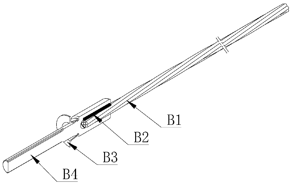
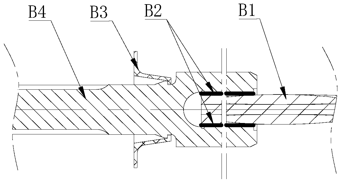
[0034] Such as figure 1 , figure 2 , image 3 and Figure 4 As shown, a flexible anchor rod of the present invention includes a flexible anchor rod body B, a tray C, a fixed torque nut D, an anti-friction washer E and an anti-twist self-aligning ball head F, wherein the tray C is arranged on the flexible anchor rod body At the tail of B, the fixed torque nut D fixes the pallet C, and an anti-friction washer E and an anti-rotation self-aligning ball head F are arranged between the pallet C and the fixed torque nut D;

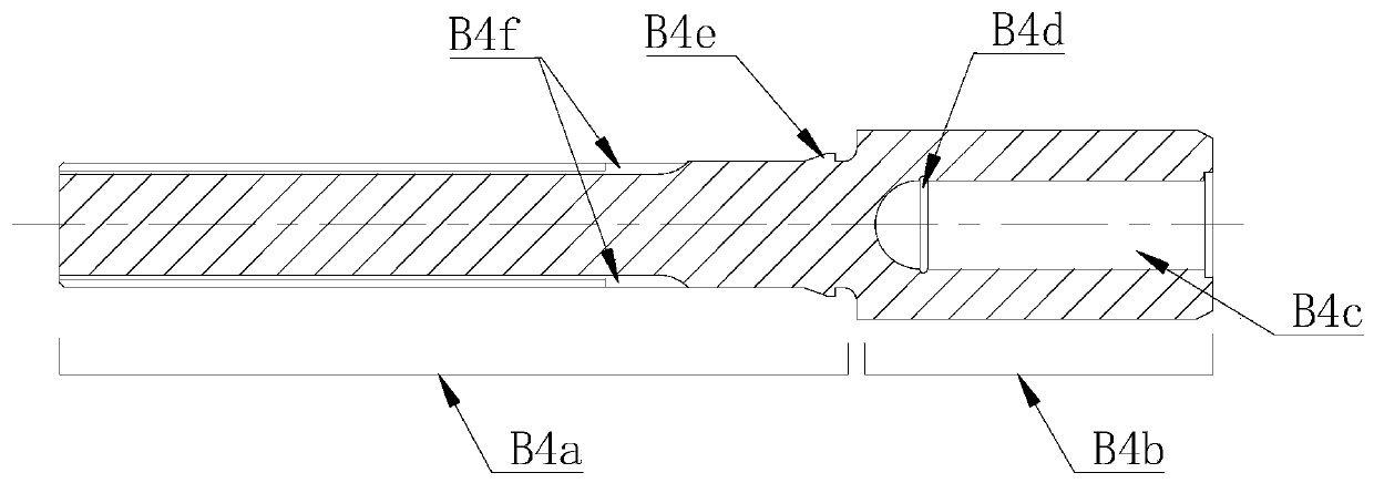
[0035] The flexible anchor body B includes a steel strand B1, and the tail end of the steel strand B1 is arranged in a connecting sleeve B4, and the connecting sleeve B4 includes a tail end B4a and a head end B4b, and a connection between the tail end B4a and the head end B4b The transition section is provided with a ring-shaped...


PUM


Abstract

The invention discloses a construction method of a flexible anchor rod, which is suitable for the field of coal mine roadway support engineering. First construct a stepped bolt hole in the rock mass; push the flexible bolt body against the anchoring agent into the bottom of the bolt stepped hole, rotate the fixed torque nut to drive the flexible bolt body and the anti-twist self-aligning ball head to rotate and advance together, Until the flanging of the limiting cylinder fits closely to the excavation surface, the bolter stops rotating and waits for the anchoring agent to solidify; it drives the fixed torque nut to rotate and destroys the fixed torque structure of the fixed torque nut, so that the fixed torque nut continues to rotate along the connecting sleeve Insert and compress the anti-friction washer, anti-twist self-aligning ball head, and tray, so that the stop column on the tray is stuck to the excavation surface to prevent the tray from rotating. Effectively prevent the rotation of the anti-twist self-aligning ball head. The anti-twist self-aligning ball head restricts the rotation of the connecting sleeve through the protrusion II and then restricts the rotation of the flexible anchor body, so that the flexible anchor body does not occur when the bolter applies pre-tightening force. turn. Its construction speed is fast and its support efficiency is high.

Description

technical field [0001] The invention relates to a construction method of a flexible anchor, in particular to a construction method of a flexible anchor used in the field of coal mine roadway support engineering. Background technique [0002] At present, bolting technology has been widely used in coal mine roadways in my country. At first, it was used in rock roadways with relatively stable surrounding rocks. Later, by improving the rigidity and strength of bolting materials, bolting technology can adapt to soft and broken surrounding rocks. Roadways, roadways affected by mining and other roadways with various harsh conditions. Bolt support mainly uses bolts to drive into the preset drilling holes in the surrounding rock of the roadway, and combines the shallow broken surrounding rock mass with the deep stable rock mass to achieve the purpose of controlling the deformation of the roadway and realizing the safety and stability of the roadway. [0003] The kind of existing anch...

Claims


Application Information

Patent Timeline
Patent Type & Authority Patents(China)
IPC IPC(8): E21D21/00E21D20/02E21D20/00
CPCE21D20/003E21D20/02E21D21/0026E21D21/006E21D21/0086
Inventor 张农谢正正魏群
Owner CHINA UNIV OF MINING & TECH
Why Eureka
Try Eureka