Guide rail for vehicle seat and vehicle seat including same

A technology of vehicle seats and guide rails, applied in vehicle seats, special positions of vehicles, vehicle components, etc., can solve problems such as expensive, noisy, and cumbersome driving mechanisms

Active Publication Date: 2021-08-17
FAURECIA
View PDF9 Cites 0 Cited by
  • Summary
  • Abstract
  • Description
  • Claims
  • Application Information

AI Technical Summary

Problems solved by technology

The disadvantage of such a motorized guideway is that the mechanical strength of the guideway in the event of an accident with the vehicle is determined by the strength of the drive mechanism
These considerations may necessitate the use of a drive mechanism that is substantially made of metal and therefore heavy, expensive and potentially noisy when subjected to vibrations from vehicle operation

Method used


Image

  • Guide rail for vehicle seat and vehicle seat including same
  • Guide rail for vehicle seat and vehicle seat including same
  • Guide rail for vehicle seat and vehicle seat including same

Examples


Embodiment Construction

[0039] In the various drawings, the same reference numerals designate the same or similar elements.

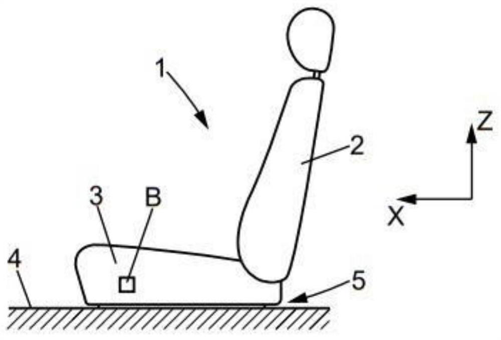
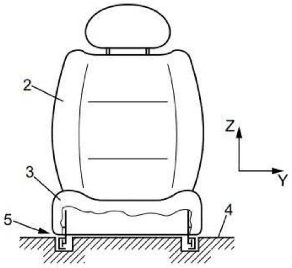
[0040] figure 1 and figure 2 Shown is a motor vehicle seat 1 comprising a backrest 2 carried by a seat portion 3 mounted on a floor 4 of the vehicle so as to slide in a substantially horizontal longitudinal direction X.

[0041] The seat part 3 is connected to the base plate 4 by two parallel rails 5 extending in the longitudinal direction X.

[0042] Each guideway 5 comprises a motorized drive mechanism which will be described below, the control of the mechanisms of the two guideways 5 being synchronously controlled by a central electronic control unit (for example, a microcontroller or similar) based on received commands, in particular from commands available to the user. Actuated two-way control button B or similar.

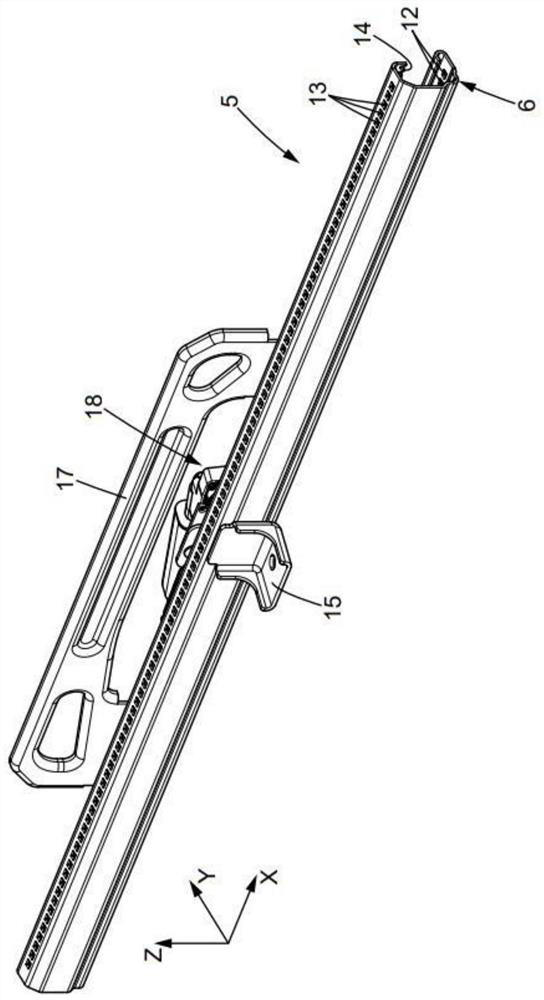
[0043] Such as Figure 3 to Figure 6 As shown, each guide rail 5 comprises first and second guide rail members 6, 16, which are mounted to slide relative...


PUM


Abstract

A track (5) for a vehicle seat includes first and second sliding track members (6, 16) driven by a drive mechanism (18, 14). The rails also include mechanical latches that are activated when an accident condition is detected.

Description

technical field [0001] The present invention relates to a guide rail for a vehicle seat and a vehicle seat comprising the guide rail. [0002] More specifically, the present invention relates to a track for a vehicle seat comprising first and second track members mounted to slide against each other in a longitudinal direction, said track having a drive mechanism which Relative movement between the first and second rail members can be induced in the longitudinal direction. Background technique [0003] Document JP2016215931A discloses an example of this type of rail. A disadvantage of such a motorized guideway is that the mechanical strength of the guideway in the event of a vehicle accident is determined by the strength of the drive mechanism. These considerations may necessitate the use of a drive mechanism that is substantially made of metal and is therefore bulky, expensive and potentially noisy when subjected to vibrations from vehicle operation. [0004] Document JP2...

Claims


Application Information

Patent Timeline
Patent Type & Authority Patents(China)
IPC IPC(8): B60N2/07B60N2/08
CPCB60N2/0722B60N2/08B60N2/067B60N2/0715B60N2/0818B60N2/43B60N2/0881B60N2/0875B60N2/0806B60N2/02246B60N2/0843B60N2/0825B60N2/2213
Inventor 法布里塞·佩蒂特文森特·纳丁卢多维克·费雷
Owner FAURECIA
Why Eureka
Try Eureka