Buoyancy adjusting device

A buoyancy adjustment and cabin technology, applied in transportation and packaging, naval ships, special-purpose vessels, etc., can solve the problems of complex overall structure, low drainage efficiency, incomplete drainage, etc., to improve drainage rate, complete drainage, and processing technology excellent effect

Active Publication Date: 2019-03-22
云南昆船机械制造有限公司
View PDF5 Cites 3 Cited by
  • Summary
  • Abstract
  • Description
  • Claims
  • Application Information

AI Technical Summary

Problems solved by technology

Based on the current buoyancy adjustment devices of most underwater devices are oil bladder type, although this design is effective, but the overall structure is too complicated, and the weight is relatively large, the drainage efficiency of the existing drainage buoyancy adjustment device is low, and the drainage Incomplete and other problems, it is necessary to improve the existing structure, it is very meaningful and necessary to provide a fast drainage buoyancy adjustment device

Method used


Image

  • Buoyancy adjusting device
  • Buoyancy adjusting device

Examples


Embodiment Construction

[0019] The following will clearly and completely describe the technical solutions in the embodiments of the present invention with reference to the accompanying drawings in the embodiments of the present invention. Obviously, the described embodiments are only some, not all, embodiments of the present invention. Based on the embodiments of the present invention, all other embodiments obtained by persons of ordinary skill in the art without making creative efforts belong to the protection scope of the present invention. In the following description, in order to clearly show the structure and working method of the present invention, the accompanying drawings will be used as the basis to describe with the help of many directional words, but "front", "rear", "left", "right", Words such as "up" and "down" are to be understood as convenient terms, and should not be understood as restrictive terms.

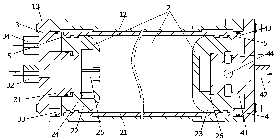
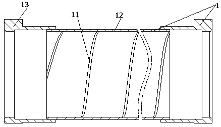
[0020] Figure 1-2 The buoyancy adjusting device shown comprises a cabin body, an a...


PUM


Abstract

The invention discloses a buoyancy adjusting device and aims to provide the buoyancy adjusting device capable of quickly draining water. The buoyancy adjusting device comprises a cabin body, an air bag positioned in the cabin body, a front cover arranged at one end of the cabin body, and a rear cover; the cabin body comprises a shell and flanges, wherein the inner wall of the shell is provided with a spiral drainage groove, and the flanges are arranged at two ends of the shell; the air bag comprises a pipe body made of rubber, an air inlet end which is in liquid-tight connection with a pipe body and is close to the front cover, and a water inlet end which is in liquid-tight connection with the pipe body and is close to the rear cover; an air inlet groove is arranged at one end of the air inlet end facing the outside of the pipe body, and a vent hole communicated with the pipe body is arranged at the bottom of the air inlet groove; the inner end of the front cover is provided with an air inlet inner ring which is hermetically connected with the air inlet groove, and the outer end of the front cover is provided with an air inlet and outlet joint which is communicated with the vent hole and is used for air inlet and outlet; the inner end of the front cover is arranged on an air inlet outer ring which is in fluid-tight fit with the inner wall of the shell, and a front gap is formedbetween the air inlet outer ring and the adjacent end surface of the air inlet joint.

Description

technical field [0001] The invention relates to the technical field of underwater equipment, in particular to a buoyancy regulating device. Background technique [0002] At present, the research and development of underwater devices has been paid more and more attention by various countries. The buoyancy adjustment device is one of the key parts. It requires the buoyancy adjustment to be very effective and reliable, and the structure should be as simple as possible and occupy less space. The rapidity and effectiveness of the buoyancy adjustment device depend on the drainage effect of the drainage structure. Based on the current buoyancy adjustment devices of most underwater devices are oil bladder type, although this design is effective, but the overall structure is too complicated, and the weight is relatively large, the drainage efficiency of the existing drainage buoyancy adjustment device is low, and the drainage Incomplete and other problems, it is necessary to improve...

Claims


Application Information

Patent Timeline
Patent Type & Authority Applications(China)
IPC IPC(8): B63G8/22
CPCB63G8/22
Inventor 张学财杨凤娟
Owner 云南昆船机械制造有限公司
Why Eureka
Try Eureka