Contact member, insert sleeve structure, and composite hole sleeve structure
A technology of contacts and hole sleeves, which is applied to the parts, connections, and electrical components of connection devices, can solve the problems of increasing contact resistance, difficulty, and multiple materials of contacts, and achieve good electrical conductivity, reduced contact resistance, and The effect of increasing the conductive cross-sectional area
- Summary
- Abstract
- Description
- Claims
- Application Information
AI Technical Summary
Problems solved by technology
Method used
Image

Examples
Embodiment 1
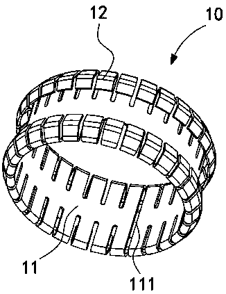
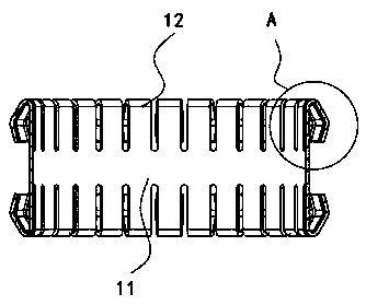
[0038] Example 1: Please refer to figure 1 with figure 2 , a contact piece 10, including a metal cylinder 11 and a plurality of bent elastic pieces 12.
[0039] A slit 111 is defined in the axial direction of the metal cylinder 11 . When the outer wall of the metal cylinder 11 is squeezed, the width of the gap 111 changes accordingly, thereby fine-tuning the diameter of the metal cylinder 11 . Therefore, it is possible to make the metal cylinder 11 enter into a slightly narrow space, and then expand the gap 111 through its own recovery ability, and at this time, the metal cylinder 11 can block the limit end of the slightly narrow space.
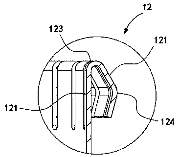
[0040] Both ends of the metal cylinder 11 are respectively provided with a plurality of separated bending elastic pieces 12 , and the bending direction of the bending elastic pieces 12 is bent from the center of the metal cylinder 11 to the outer wall of the metal cylinder 11 .
[0041] When the external pin is inserted, the pin touches t...
Embodiment 2
[0046] Example 2: Please refer to Figure 4-Figure 6 , On the basis of the first embodiment, this technical solution also provides a socket structure, including the socket 20 and the contact piece 10 disclosed in the first embodiment.
[0047] One end of the socket 20 is provided with a receiving groove 21 , and at least one first annular groove 22 is defined on the groove wall of the receiving groove 21 . Through the above method of compressing the gap 111 , the contact piece 10 is squeezed into the first annular groove 22 with a slight inclination.
[0048] Since the distance from the metal cylinder 11 to the second bent portion 124 in this embodiment is greater than the depth of the first annular groove 22 , the axial length of the contact member 10 is greater than the width of the first annular groove 22 . Therefore, when the second bent portion 124 is in contact with the bottom of the first annular groove 22, the second end portion 122 touches the notch of the first annu...
Embodiment 3
[0051] Example 3: Please refer to Figure 10-Figure 12 , On the basis of the first embodiment, the present technical solution also provides a composite socket structure, including the socket 40, the rotating spring 50, a plurality of hollow glands 60 and the contact piece 10 disclosed in the first embodiment.
[0052] In this embodiment, the diameter of both ends of the rotating spring 50 is larger, and the diameter of the middle part is smaller. The middle part of the inner wall of the hole sleeve 40 is provided with a second annular groove 41 .
[0053] The contact piece 10 is sheathed in the middle of the rotating spring 50 , and both of them are set in the hole sleeve 40 . The contact piece 10 is correspondingly snapped into the second annular groove 41 . The hollow pressing cover 60 presses the end of the rotary spring 50 and the end of the hole sleeve 40 together.
[0054] The installation method of this composite grommet 40 is as follows:
[0055] First, the gap 111 ...
PUM
 Abstract
Description
Claims
Application Information
 - R&D
- Intellectual Property
- Life Sciences
- Materials
- Tech Scout
- Unparalleled Data Quality
- Higher Quality Content
- 60% Fewer Hallucinations
Browse by: Latest US Patents, China's latest patents, Technical Efficacy Thesaurus, Application Domain, Technology Topic, Popular Technical Reports.
© 2025 PatSnap. All rights reserved.Legal|Privacy policy|Modern Slavery Act Transparency Statement|Sitemap|About US| Contact US: help@patsnap.com