A suspended drop test device for rocket recovery

A test device and suspension technology, which is applied to the landing device of space navigation vehicle, the system, transportation and packaging of space navigation vehicle returning to the earth's atmosphere, which can solve the problems of lack of rocket landing support mechanism and so on.

Active Publication Date: 2021-10-01
HARBIN INST OF TECH
View PDF24 Cites 0 Cited by
  • Summary
  • Abstract
  • Description
  • Claims
  • Application Information

AI Technical Summary

Problems solved by technology

[0003] In order to solve the problem that the existing rocket landing support mechanism lacks a device for simulating the movement of the landing support mechanism to verify the reliability of each component of the landing support mechanism, the present invention provides a suspension drop test device for rocket recovery

Method used


Image

  • A suspended drop test device for rocket recovery
  • A suspended drop test device for rocket recovery
  • A suspended drop test device for rocket recovery

Examples


specific Embodiment approach 1

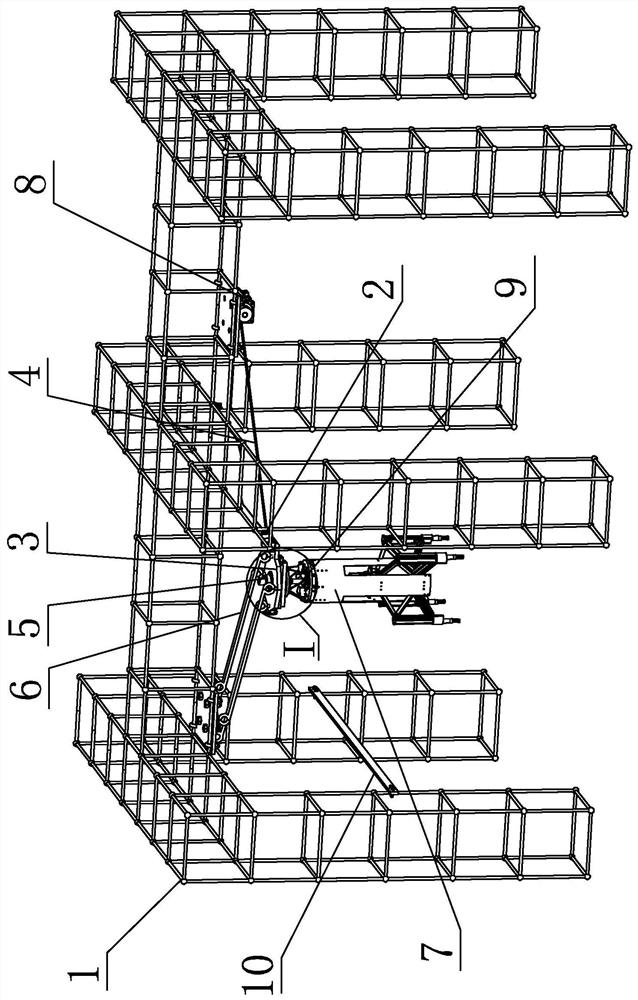
[0025] Specific implementation mode one: combine figure 1 To illustrate this embodiment, this embodiment includes a bracket 1, a cable-stayed release mechanism 2, a connecting plate 3, a cable-stayed wire rope 4, a flat throw release mechanism 5 and a traction wire rope 6;

[0026] One end of the cable-stayed steel wire rope 4 is connected to the bracket 1, and the other end of the cable-stayed steel wire rope 4 is connected to the cable-stayed release mechanism 2. The cable-stayed release mechanism 2 is hinged to the connecting plate 3, and the connecting plate 3 is connected to the bracket 1 through the traction steel wire rope 6. Plate 3 is provided with flat-throwing release mechanism 5, and flat-throwing release mechanism 5 is connected with landing support mechanism 7, and traction wire rope 6 is set at a certain angle with obliquely-stayed wire rope 4 so that landing support mechanism 7 is suspended in the air.

specific Embodiment approach 2

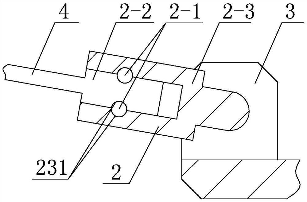
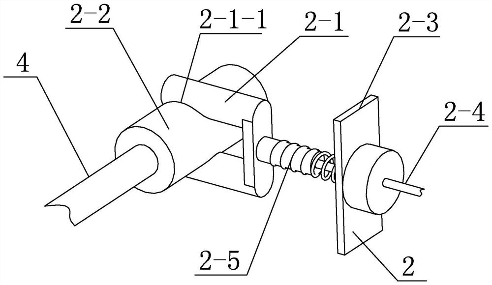
[0027] Specific implementation mode two: combination Figure 2-Figure 4 To illustrate this embodiment, the cable-stayed release mechanism 2 of this embodiment includes a release lock 2-1, a cylindrical pin 2-2, a housing 2-3, a release rope 2-4, and a compression spring 2-5;

[0028] The shell 2-3 is hinged with the connecting plate 3, and the shell 2-3 is processed with a hole, the hole of the shell 2-3 is provided with a cylindrical pin 2-2, and the hole of the shell 2-3 and the cylindrical pin 2-2 are respectively processed with Draw-in groove 231, the draw-in groove 231 on the hole of shell 2-3 cooperates with the draw-in groove 231 on the cylindrical pin 2-2 and can accommodate release lock 2-1 to slide in draw-in groove 231, release the sliding direction of lock 2-1 Perpendicular to the axis of the cylindrical pin 2-2, the release lock 2-1 is arranged in the housing 2-3, and the release lock 2-1 is processed with a release notch 2-1-1 matching the hole on the housing 2-3...

specific Embodiment approach 3

[0032] Specific implementation mode three: combination Figure 5-Figure 7 To illustrate this embodiment, the flat throw release mechanism 5 in this embodiment includes an electromagnetic actuator 5-1, a claw 5-2 and a limit clamp 5-3;

[0033] The electromagnetic actuator 5-1 is arranged on the connection plate 3, the action execution end of the electromagnetic actuator 5-1 is fixed with a claw 5-2 and can move up and down, and the limit clamp plate 5-3 is horizontally slidably arranged on the connection plate 3 , the claw 5-2 cooperates with the limit clamp plate 5-3;

[0034] An attitude control mechanism 9 is arranged below the limit clamping plate 5 - 3 , and the attitude control mechanism 9 is connected with the landing support mechanism 7 .

[0035] Before the landing support mechanism 7 is released, the claw 5-2 cooperates with the limit clamp plate 5-3 to limit the landing support mechanism 7. After the landing support mechanism 7 is released, the landing support mech...


PUM


Abstract

A suspension drop test device for rocket recovery, which relates to a suspension drop test device to solve the lack of existing rocket landing support mechanism to simulate the movement of the landing support mechanism to verify the reliability of the components of the landing support mechanism device problem. The invention comprises a bracket, a cable-stayed release mechanism, a connecting plate, a cable-stayed steel wire rope, a flat throw release mechanism and a traction steel wire rope; one end of the cable-stayed steel wire rope is connected to the bracket, and the other end of the cable-stayed steel rope is connected to the cable-stayed release mechanism, and the cable-stayed release mechanism The mechanism is hinged with the connecting plate, the connecting plate is connected with the bracket through the traction wire rope, and the flat throwing release mechanism is arranged on the connecting plate, and the flat throwing release mechanism is connected with the landing support mechanism. up in the air. The invention is suitable for simulating the motion of the landing support mechanism on the rocket to verify the reliability of each component on the landing support mechanism.

Description

technical field [0001] The invention relates to a suspended falling body testing device, in particular to a suspended falling body testing device used for rocket recovery. Background technique [0002] The prospect of commercial aerospace development is promising. With the integration of military and civilians, my country has accelerated the development of private aerospace. At present, most of the launch rockets are for one-time use. Recycling rockets through development is a powerful way to reduce launch costs, and the rocket landing support mechanism is As one of the key technologies of recoverable rockets, designing a landing support mechanism with high reliability is the premise and guarantee for completing the recovery work. After the development of the rocket landing support mechanism is completed, it is necessary to accumulate launch data through ground tests and verify the reliability of component selection. At present, there is no device that can simulate the movem...

Claims


Application Information

Patent Timeline
Patent Type & Authority Patents(China)
IPC IPC(8): B64G1/62B64G1/66
CPCB64G1/62B64G1/66
Inventor 于海涛高海波田保林李楠刘振邓宗全
Owner HARBIN INST OF TECH
Why Eureka
Try Eureka