Suspending falling testing device used for rocket recovery
A test device and suspension technology, which is applied to the landing device of the spacecraft, the system, transportation and packaging of the spacecraft returning to the earth's atmosphere, which can solve the problems of lack of support mechanism for rocket landing
- Summary
- Abstract
- Description
- Claims
- Application Information
AI Technical Summary
Problems solved by technology
Method used
Image
Examples
specific Embodiment approach 1
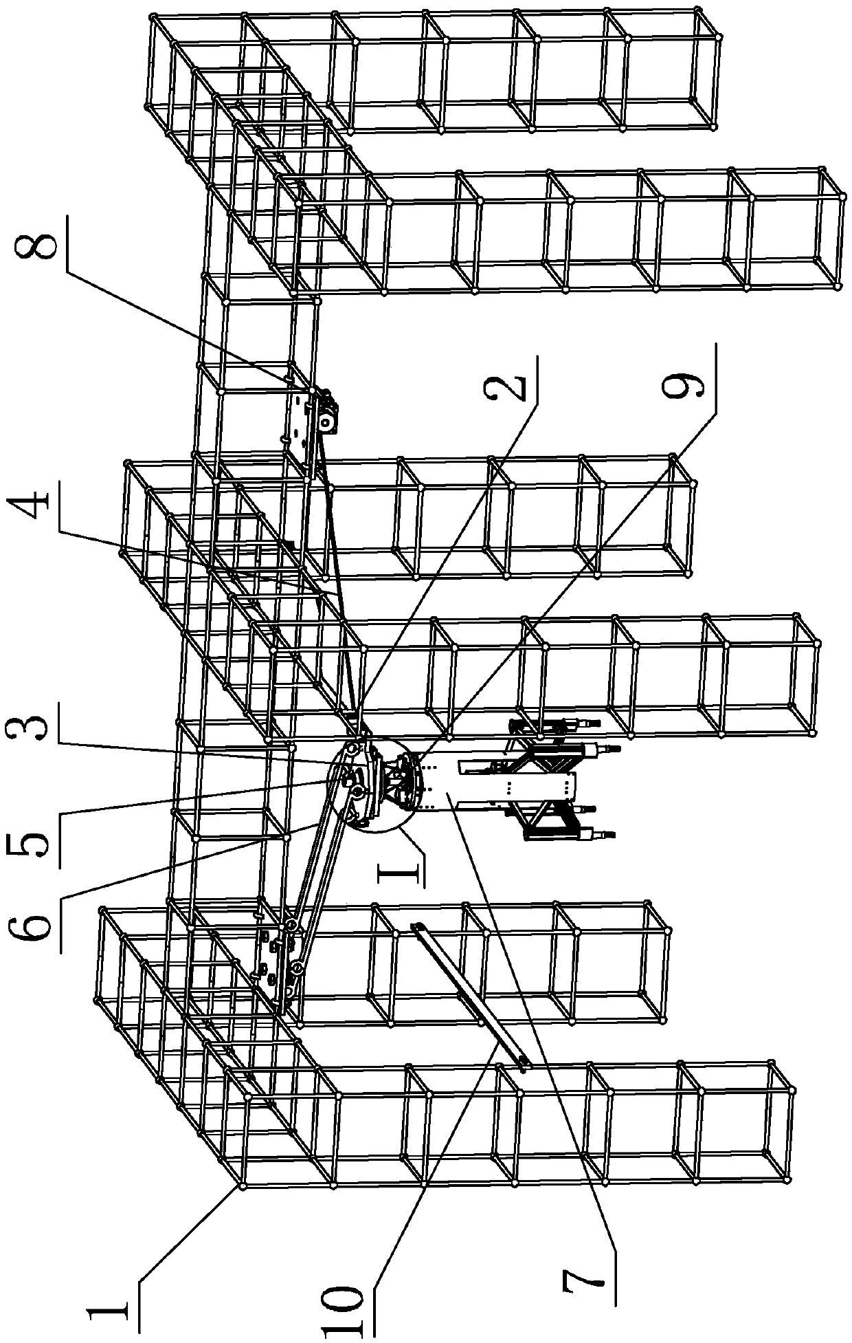
[0025] Specific implementation mode one: combine figure 1 To illustrate this embodiment, this embodiment includes a bracket 1, a cable-stayed release mechanism 2, a connecting plate 3, a cable-stayed wire rope 4, a flat throw release mechanism 5 and a traction wire rope 6;
[0026] One end of the cable-stayed steel wire rope 4 is connected to the bracket 1, and the other end of the cable-stayed steel wire rope 4 is connected to the cable-stayed release mechanism 2. The cable-stayed release mechanism 2 is hinged to the connecting plate 3, and the connecting plate 3 is connected to the bracket 1 through the traction steel wire rope 6. Plate 3 is provided with flat-throwing release mechanism 5, and flat-throwing release mechanism 5 is connected with landing support mechanism 7, and traction wire rope 6 is set at a certain angle with obliquely-stayed wire rope 4 so that landing support mechanism 7 is suspended in the air.
specific Embodiment approach 2
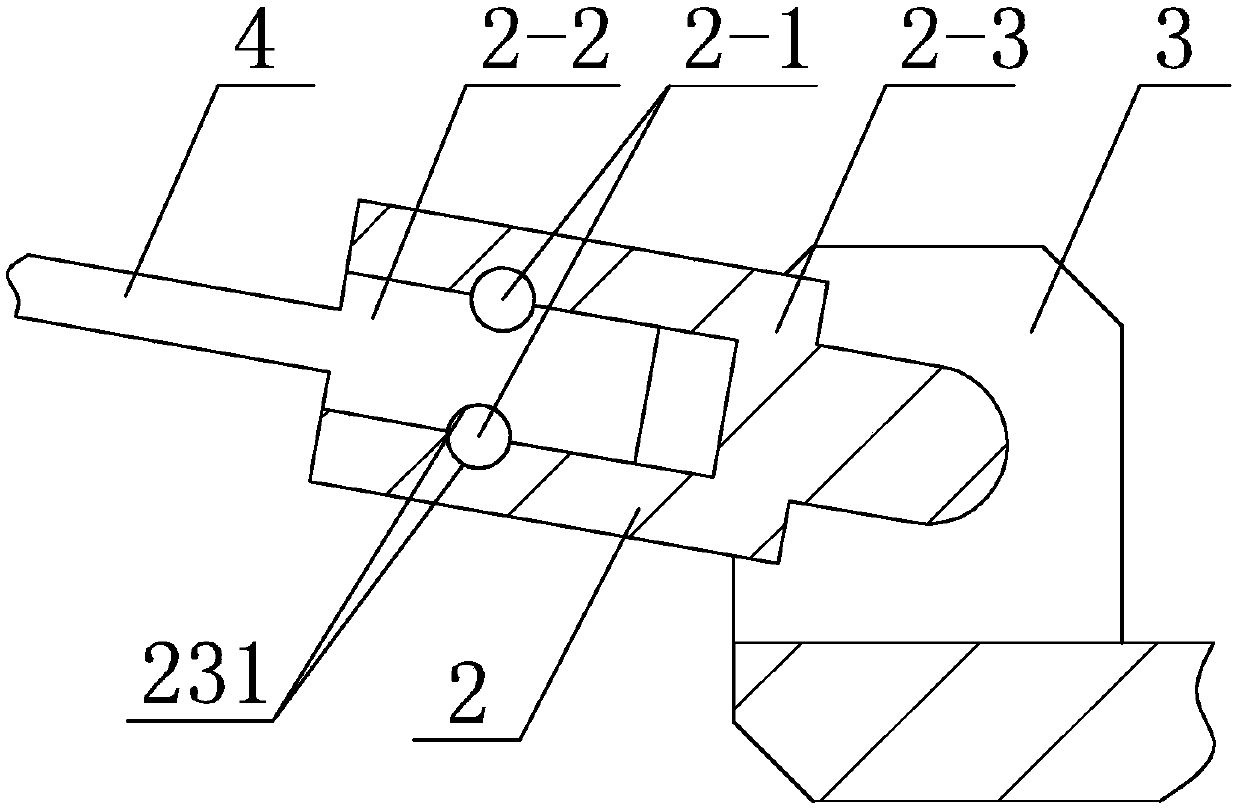
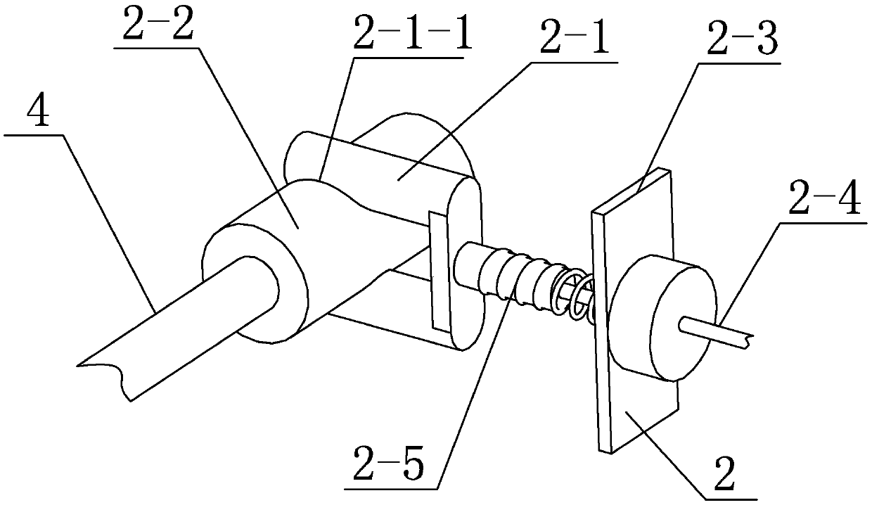
[0027] Specific implementation mode two: combination Figure 2-Figure 4 To illustrate this embodiment, the cable-stayed release mechanism 2 of this embodiment includes a release lock 2-1, a cylindrical pin 2-2, a housing 2-3, a release rope 2-4, and a compression spring 2-5;
[0028] The shell 2-3 is hinged with the connecting plate 3, and the shell 2-3 is processed with a hole, the hole of the shell 2-3 is provided with a cylindrical pin 2-2, and the hole of the shell 2-3 and the cylindrical pin 2-2 are respectively processed with Draw-in groove 231, the draw-in groove 231 on the hole of shell 2-3 cooperates with the draw-in groove 231 on the cylindrical pin 2-2 and can accommodate release lock 2-1 to slide in draw-in groove 231, release the sliding direction of lock 2-1 Perpendicular to the axis of the cylindrical pin 2-2, the release lock 2-1 is arranged in the housing 2-3, and the release lock 2-1 is processed with a release notch 2-1-1 matching the hole on the housing 2-3...
specific Embodiment approach 3
[0032] Specific implementation mode three: combination Figure 5-Figure 7 To illustrate this embodiment, the flat throw release mechanism 5 in this embodiment includes an electromagnetic actuator 5-1, a claw 5-2 and a limit clamp 5-3;
[0033] The electromagnetic actuator 5-1 is arranged on the connection plate 3, the action execution end of the electromagnetic actuator 5-1 is fixed with a claw 5-2 and can move up and down, and the limit clamp plate 5-3 is horizontally slidably arranged on the connection plate 3 , the claw 5-2 cooperates with the limit clamp plate 5-3;
[0034] An attitude control mechanism 9 is arranged below the limit clamping plate 5 - 3 , and the attitude control mechanism 9 is connected with the landing support mechanism 7 .
[0035] Before the landing support mechanism 7 is released, the claw 5-2 cooperates with the limit clamp plate 5-3 to limit the landing support mechanism 7. After the landing support mechanism 7 is released, the landing support mech...
PUM
 Abstract
Description
Claims
Application Information
 - R&D
- Intellectual Property
- Life Sciences
- Materials
- Tech Scout
- Unparalleled Data Quality
- Higher Quality Content
- 60% Fewer Hallucinations
Browse by: Latest US Patents, China's latest patents, Technical Efficacy Thesaurus, Application Domain, Technology Topic, Popular Technical Reports.
© 2025 PatSnap. All rights reserved.Legal|Privacy policy|Modern Slavery Act Transparency Statement|Sitemap|About US| Contact US: help@patsnap.com


