
Posture simulation system and method for rotary wing unmanned aerial vehicle

A technology of unmanned rotor and simulation system, which is applied in the field of UAV simulation/testing devices, can solve problems such as increasing the difficulty of structural design, misalignment of rotation centers, and decrease in frame strength and stiffness, so as to achieve better simulation effect and smaller size. The effect of small restrictions and good simulation effects

Pending Publication Date: 2019-02-22
智灵飞(北京)科技有限公司
View PDF0 Cites 1 Cited by
  • Summary
  • Abstract
  • Description
  • Claims
  • Application Information

AI Technical Summary

Problems solved by technology

[0005] (1) The scope of the test object, the strength of the frame, and the influence on the dynamics of the UAV are mutually restricted. The rotation centers of the three degrees of freedom of the device do not coincide, and the relative position of the aircraft cannot be adjusted so that the center of mass of the aircraft coincides with the rotation center of the device.
[0006] (2) The size of the frame of the existing external frame device limits the size of the object to be measured. Increasing the size of the frame will reduce the strength and stiffness of the frame. The influence of
[0007] The difficulty and significance of solving the above technical problems: To solve the above problems, the outer frame design must be abandoned first, which can solve the problem of accurate measurement of the flight performance of large-scale aircraft, and at the same time take into account the detection of flight data, so that the angle sensor needs to be synchronized with the equipment. shaft installation, it is difficult to solve the problem of placement of sensors for monitoring various flight data, which greatly increases the difficulty of structural design
And in order to obtain real flight data, the center of mass of the aircraft, the center of mass of the equipment and the center of rotation of the equipment must be coincident, which further increases the difficulty of structural design

Method used


Image

  • Posture simulation system and method for rotary wing unmanned aerial vehicle
  • Posture simulation system and method for rotary wing unmanned aerial vehicle
  • Posture simulation system and method for rotary wing unmanned aerial vehicle

Examples


Embodiment Construction

[0025] In order to further understand the content, features and effects of the present invention, the following examples are given, and detailed descriptions are given below with reference to the accompanying drawings.

[0026] The structure of the present invention will be described in detail below in conjunction with the accompanying drawings.

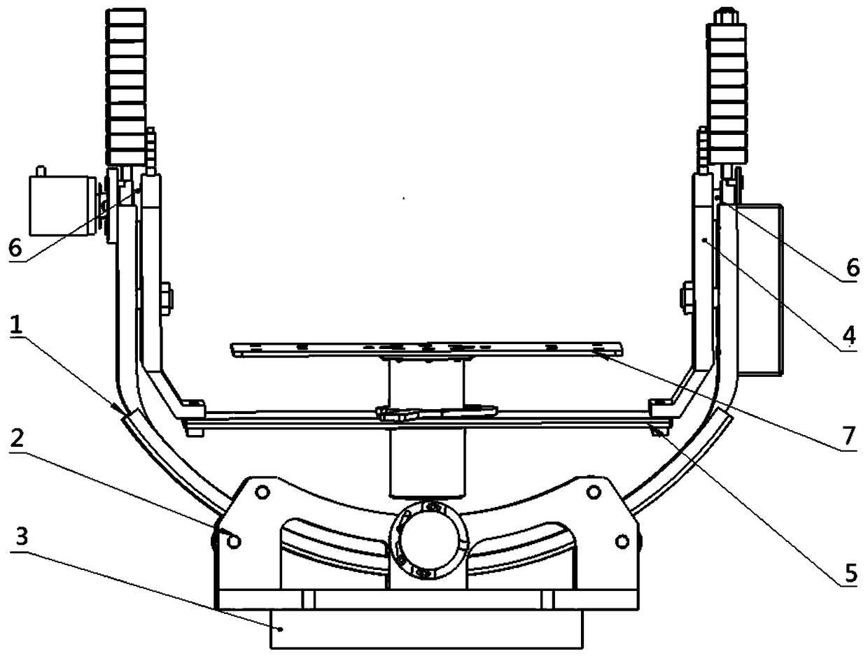
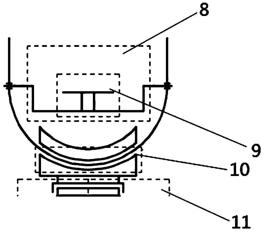
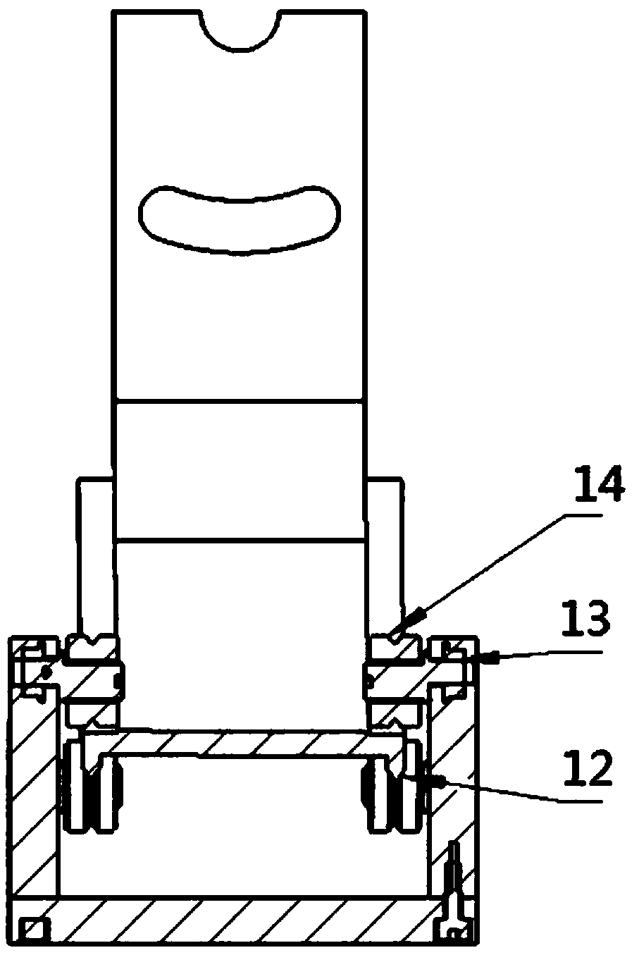
[0027] like Figure 1-Figure 4 As shown, the attitude simulation system for the rotor UAV provided by the embodiment of the present invention includes: guide rail seat 1, fixing screw (bearing is equipped with outside) 2, rotating outer ring 3, rotating arm 4, rotating plate 5, rotating shaft 6 , Lifting plate 7, the third rotating device 8, mounting device 9, the second rotating device 10, the first rotating device 11, guide rail 12, bearing 13, v-groove pulley 14.

[0028] The first rotating device 11 includes: a rotary inner ring and a rotary outer ring 3;

[0029] The second rotating device 10 comprises: a guide rail seat 1, a ...


PUM


Abstract

The invention belongs to the technical field of unmanned aerial vehicle simulation / testing devices, and discloses a posture simulation system and method for a rotary wing unmanned aerial vehicle. Theposture simulation system is provided with a rotation inner ring, and the rotation inner ring is connected with a supporting device through a bolt; the rotation inner ring is positioned in a rotationouter ring; the rotation inner ring and the rotation outer ring form a bearing-similar structure and can relatively rotate; the rotation outer ring and a rotating device base are connected through a bolt; V-shaped pulleys are fixed to the rotating device base through fixed set screws; and the V-shaped pulleys are fixed to the upper and lower sides of a guide rail seat and are used for clamping theguide rail seat. According to the posture simulation system, simulation of three degrees of freedom of the rotary wing unmanned aerial vehicle can be achieved, rotation centers of the three degrees of freedom coincide with one another, and simulation of yawing, pitching and overturning flying postures of the unmanned aerial vehicle is achieved; and simulation of motion of the three degrees of freedom is achieved through three rotating devices, the three rotating devices adopt bearings, additional friction force of the rotating devices is quite small, and a better simulation effect is achieved.

Description

technical field [0001] The invention belongs to the technical field of unmanned aerial vehicle simulation / testing devices, and in particular relates to a system and method for attitude simulation of a rotor unmanned aerial vehicle. Background technique [0002] At present, the existing technologies commonly used in the industry are as follows: [0003] The development of domestic ground debugging equipment for UAVs is insufficient. The size of the frame of the existing external frame device limits the size of the measured object. If the frame size is increased when the frame thickness is the same, the frame length will It will reduce the strength and rigidity of the frame; this will reduce the stability of the structure, and the aircraft may vibrate up and down after running on the device, resulting in distortion of the measurement structure. However, increasing the strength of the frame by introducing a reinforced structure will increase the weight of the entire test equip...

Claims


Application Information

Patent Timeline
IPC IPC(8): B64F5/60
CPCB64F5/60
Inventor 宋晓东武斌韩冬桑晨水晓冰黄国限桑涛
Owner 智灵飞(北京)科技有限公司
Learn More