Bearing oil return structure

A bearing lubricating oil and bearing technology, which is applied in the direction of engine lubrication, turbine/propulsion lubrication, engine components, etc., can solve the problems of increased engine weight, increased number of engine parts, and coking of lubricating oil, so as to avoid lubricating oil. The effect of coking and improving work performance

Active Publication Date: 2020-06-19
AECC HUNAN AVIATION POWERPLANT RES INST
View PDF6 Cites 0 Cited by
  • Summary
  • Abstract
  • Description
  • Claims
  • Application Information

AI Technical Summary

Problems solved by technology

[0003] The invention provides a bearing oil return structure to solve the technical problems that the existing oil return structure requires a large installation space, increases the number of engine parts, increases the weight of the engine, and cokes a large amount of lubricating oil in the oil collection pool

Method used


Image

  • Bearing oil return structure
  • Bearing oil return structure
  • Bearing oil return structure

Examples


Embodiment Construction

[0025] The embodiments of the present invention will be described in detail below with reference to the accompanying drawings, but the present invention can be implemented in many different ways defined and covered by the claims.

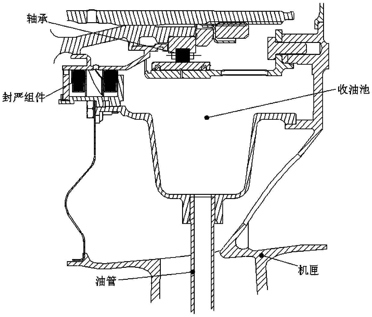
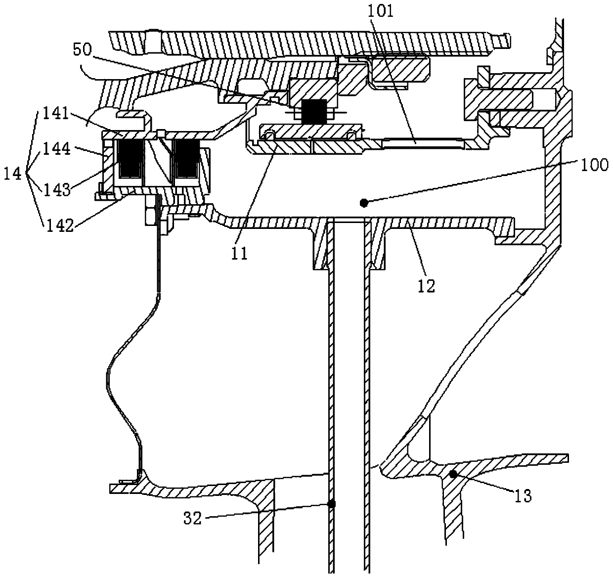
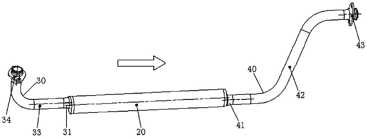
[0026] refer to figure 2 and image 3 , the preferred embodiment of the present invention provides a bearing lubricating oil oil return structure, including: a ring-shaped bearing ring cavity 100 surrounding the bearing 50, the bearing ring cavity 100 communicates with the bearing 50 to receive the lubricating bearing 50 of lubricating oil. The bearing ring chamber 100 is connected with an oil return pipe group, which is connected with an oil return pump (not shown in the figure), and the oil return pipe group is used to guide the lubricating oil entering the bearing ring chamber 100 into the oil return pump when the engine is in normal operation, and the oil return pipe group is used to guide the lubricating oil entering the bearing ring chamber ...


PUM


Abstract

The invention discloses a bearing grease return structure comprising an annular bearing ring cavity arranged outside a bearing in a surrounding mode. The bearing ring cavity communicates with the bearing so as to receive grease lubricating the bearing. A grease return pipe set is connected to the bearing ring cavity and is connected with a grease return pump. The grease return pipe set is used forguiding grease entering the bearing ring cavity into the grease return pump when an engine works normally, and for storing grease after the engine is stopped so as to prevent the grease from being held in the bearing ring cavity. In the bearing grease return structure, no large-volume grease receiving pool structure is needed, therefore no large installing space is needed in a case, the structureof an original engine is not changed, and the number of engine parts and the weight of the engine are not increased. In addition, after the engine is stopped, the bearing grease is stored in the grease return pipe set away from the turbine end, no grease is in the bearing ring cavity, thus grease coking in the bearing ring cavity can be avoided effectively, and then work performance of an enginelubrication system is improved greatly.

Description

technical field [0001] The invention relates to the field of aero-engines, in particular to a bearing lubricating oil return structure. Background technique [0002] In the fields of aero-engines and gas turbines, a large amount of lubricating oil is required for lubrication and cooling when the bearings are working, and when the machine stops running, a large amount of residual oil needs to be stored. The existing oil collection structure is the structure of the bearing cavity oil collection pool, such as figure 1 As shown, the structure is based on the existing bearing cavity, and the bearing cavity is designed as a large-volume oil collection tank to ensure the collection and storage of residual oil. However, the large-volume oil collection tank requires a large installation space inside the casing to accommodate the oil collection tank; and the design of the oil collection tank will change the original engine structure and increase the number of engine parts and the wei...

Claims


Application Information

Patent Timeline
Patent Type & Authority Patents(China)
IPC IPC(8): F02C7/06
CPCF02C7/06
Inventor 唐伟员覃华斌胡宁吴浩谭元球胡燕华
Owner AECC HUNAN AVIATION POWERPLANT RES INST
Why Eureka
Try Eureka