Auxiliary fixing clamp for test joints

A technology for testing joints and fixing clips, which is applied in the direction of measuring devices, measuring electrical variables, measuring device shells, etc. It can solve the problems that the test joints cannot be guaranteed to be in stable and effective contact with the terminals to be tested on the terminal block, and achieve stable and effective contact.

Pending Publication Date: 2019-04-09
GUANGDONG POWER GRID CO LTD +1
View PDF0 Cites 2 Cited by
  • Summary
  • Abstract
  • Description
  • Claims
  • Application Information

AI Technical Summary

Problems solved by technology

[0005] In order to overcome the defect that the circuit breaker test auxiliary fixture described in the prior art cannot ensure stable and effective contact between the test joint and the terminal to be tested on the terminal row, the present invention provides an auxiliary test joint fixing clamp

Method used


Image

  • Auxiliary fixing clamp for test joints
  • Auxiliary fixing clamp for test joints
  • Auxiliary fixing clamp for test joints

Examples


Embodiment 1

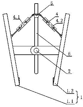
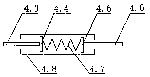
[0034] This embodiment provides an auxiliary fixing clip for a test joint, such as Figure 1-4 As shown, the fixed clip includes: a clip body 1, a connecting shaft 2, a clamping spring 3, an elastic arm 4, and a fixing device 5; the clip body 1 includes a first clip body 1.1 and a second clip body 1.2; the elastic arm 4 includes The first elastic arm 4.1, the second elastic arm 4.2; the first clamp body 1.1 and the second clamp body 1.2 are connected by the connecting shaft 2, the connecting shaft 2 is sleeved with a clamping spring 3, and the two protruding ends of the clamping spring 3 Press the first clip body 1.1 and the second clip body 1.2 respectively to make the first clip body 1.1 and the second clip body 1.2 in a clamping state; the clamping ends of the first clip body 1.1 and the second clip body 1.2 in the clip body 1 are The clamping end, the other end is the hand-held end; the first clamp body 1.1 and the second clamp body 1.2 near the hand-held end are respectivel...

Embodiment 2

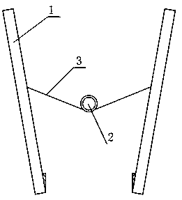
[0044] This embodiment provides an auxiliary fixing clip for a test joint, such as Figure 3-6 As shown, the fixed clip includes: a clip body 1, a connecting shaft 2, a clamping spring 3, an elastic arm 4, and a fixing device 5; the clip body 1 includes a first clip body 1.1 and a second clip body 1.2; the elastic arm 4 includes The first elastic arm 4.1, the second elastic arm 4.2; the first clamp body 1.1 and the second clamp body 1.2 are connected by the connecting shaft 2, the connecting shaft 2 is sleeved with a clamping spring 3, and the two protruding ends of the clamping spring 3 Press the first clip body 1.1 and the second clip body 1.2 respectively to make the first clip body 1.1 and the second clip body 1.2 in a clamping state; the clamping ends of the first clip body 1.1 and the second clip body 1.2 in the clip body 1 are The clamping end, the other end is the hand-held end; the first clamp body 1.1 and the second clamp body 1.2 near the hand-held end are respective...


PUM


Abstract

The invention relates to an auxiliary fixing clamp for test joints. The auxiliary fixing clamp comprises a first clamp body, a second clamp body, a connection shaft, a clamping spring, a first elasticarm, a second elastic arm and a fixing device, wherein the first clamp body and the second clamp body are connected through the connection shaft; the connection shaft is sleeved by the clamping spring; two extension ends of the clamping spring respectively press the first clamp body and the second clamp body to ensure that the first clamp body and the second clamp body are located in a clamping state; the handheld ends of the first clamp body and the second clamp body are respectively connected with one end of the first elastic arm and one end of the second elastic arm; the other end of the first elastic arm and the other end of the second elastic arm are respectively connected with the fixing device; after the connection, an included angle formed by the clamping ends of the first elasticarm and the second elastic arm is smaller than 180 degrees; the fixing device is used for fixing test joints; and a through hole for the passing of the test joints fixed by the fixing device is formed in the connection shaft. The auxiliary fixing clamp is capable of ensuring that the contact between test joints and to-be-tested terminals on terminals strips is stable and effective during breakertest.

Description

Technical field [0001] The invention relates to the field of power test auxiliary devices, and more specifically, to an auxiliary fixing clip for a test joint. Background technique [0002] The terminal block means the insulating part that carries multiple or more sets of mutually insulated terminal assemblies and is used to fix the support; the function of the terminal block is to connect the lines of the equipment in the screen and the equipment outside the screen to play a signal (current and voltage) The function of transmission; with the terminal block, the wiring is beautiful and easy to maintain. The connection between the long-distance lines is mainly reliable, and the construction and maintenance are convenient. [0003] In the circuit breaker test, the circuit breaker is usually tested with the terminal from the circuit breaker to the terminal block as the test contact; however, during the test process, the worker needs to hold the test connector by hand to prevent it fro...

Claims


Application Information

Patent Timeline
Patent Type & Authority Applications(China)
IPC IPC(8): G01R1/04
CPCG01R1/0425
Inventor 王俊波武利会刘志陆黎小龙李国伟李慧唐琪罗容波陈贤熙吴小平陈志平邱太洪李新黄育龙董镝
Owner GUANGDONG POWER GRID CO LTD
Why Eureka
Try Eureka