Check patentability & draft patents in minutes with Patsnap Eureka AI!

Imaging apparatus

A camera device, camera element technology, applied in photography, image communication, signal generator with a single pick-up device, etc.

Active Publication Date: 2019-04-16
NIKON CORP
View PDF6 Cites 1 Cited by
  • Summary
  • Abstract
  • Description
  • Claims
  • Application Information

AI Technical Summary

Problems solved by technology

[0003] However, in conventional imaging devices, it is necessary to obtain image data at multiple focus positions

Method used


Image

  • Imaging apparatus
  • Imaging apparatus
  • Imaging apparatus

Examples


Embodiment Construction

[0016] Hereinafter, the present invention will be described through embodiments of the invention, but the following embodiments are not limited to the invention described in the claims. In addition, all combinations of the features described in the embodiments are not necessarily essential to the solution of the invention.

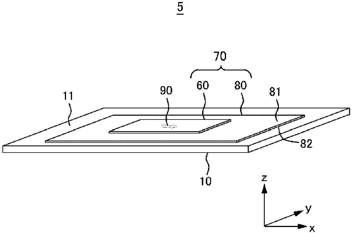
[0017] figure 1 A usage example of the microscope system 5 of the first embodiment is schematically shown. The microscope system 5 includes a microscope device 10 and a microscope specimen 70 . The microscope device 10 photographs a sample 90 placed on a microscope specimen 70 . In addition, the microscope system 5 is an example of an imaging system. The microscope device 10 is an example of an imaging device. Sample 90 is an example of a subject.

[0018] The microscope specimen 70 has a slide 80 and a coverslip 60 . The cover glass 60 and the slide glass 80 are light-transmitting. A sample 90 is placed on the slide glass 80 . The sample 90 is san...


PUM


Abstract

This imaging apparatus comprises: an imaging device having a plurality of photoelectric conversion elements; a plurality of light-receiving ports; and a plurality of light-emitting ports, wherein theplurality of light-receiving ports and light-emitting ports are provided for each of the plurality of photoelectric conversion elements. The imaging apparatus is provided with a light restriction unitwhich emits to each of the plurality of photoelectric conversion elements, the light which, among light entering each of the plurality of light-receiving ports, is able to reach each of the pluralityof light-emitting ports, and prevents the light that is unable to reach each of the plurality of light-emitting ports from being emitted to each of the plurality of photoelectric conversion elements.

Description

technical field [0001] The present invention relates to imaging devices. Background technique [0002] Conventionally, there is known an imaging device that generates an omni-focus image of a subject. [0003] However, in conventional imaging devices, it is necessary to acquire image data at a plurality of focus positions. [0004] prior art literature [0005] patent documents [0006] Patent Document 1: Japanese Patent Laid-Open No. 2005-99736 Contents of the invention [0007] In the first aspect, the imaging device has: an imaging element having a plurality of photoelectric conversion elements; Among the lights that reach the plurality of light entrances, the lights that can reach the plurality of light exits are respectively emitted to the plurality of photoelectric conversion elements, and the lights that cannot reach the respective plurality of light exits are restricted from being sent to the plurality of photoelectric conversion elements respectively. shoot. ...

Claims


Application Information

Patent Timeline
IPC IPC(8): H04N5/369G02B21/00G03B15/00H04N5/225H04N9/07
CPCG02B21/365H04N23/55H04N25/70H04N23/10G03B15/00H04N23/12H04N23/45H04N25/76G02B21/008G02B21/34G03B15/02
Inventor 纲井史郎
Owner NIKON CORP
Features
  • R&D
  • Intellectual Property
  • Life Sciences
  • Materials
  • Tech Scout
  • Unparalleled Data Quality
  • Higher Quality Content
  • 60% Fewer Hallucinations
Learn More