A shaft end surface printing mechanism and its use method

A technology of printing mechanism and shaft end face, which is used in typewriters, printing devices, printing and other directions, can solve problems such as the inability to effectively adjust the distance between the print head and the shaft end face, the inability to accurately position the marking machine, and the inability to fix shaft parts, etc. Achieve the effect of solving the inability to efficiently and accurately print, high practicability and versatility, and reducing operating costs

Active Publication Date: 2019-11-15
江苏盘石机械科技有限公司
View PDF7 Cites 0 Cited by
  • Summary
  • Abstract
  • Description
  • Claims
  • Application Information

AI Technical Summary

Problems solved by technology

However, when printing the end face of the shaft, the general-purpose marking machine is still used, which cannot fix the shaft parts well, and because the printing operation needs to be performed on the side end face of the shaft part, the marking machine cannot be accurately fixed. At the same time, due to the marking operation, the individual printed marks need to be specially marked, which requires marks of different depths, and the current marking machine cannot effectively adjust the distance between the printing head and the end face of the shaft, and the operation process is extremely difficult. It is cumbersome and the printing effect is not ideal

Method used


Image

  • A shaft end surface printing mechanism and its use method
  • A shaft end surface printing mechanism and its use method
  • A shaft end surface printing mechanism and its use method

Examples


Embodiment 1

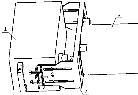
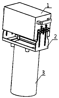
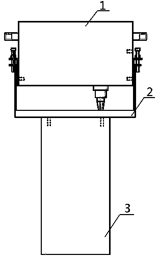
[0024] The shaft end surface printing mechanism includes a printing device 1 and a supporting device 2, the printing device 1 can be detachably connected to the supporting device 2, the supporting device 2 can be supported on the shaft part 3, and the printing head of the printing device 1 passes through the supporting device 2. Print the end face of the shaft part 3.

Embodiment 2

[0026] The printing device 1 includes a rectangular housing 1-1. The front side of the rectangular housing 1-1 is in the form of an opening, and the other sides are assembled from plates. The plates can be stainless steel plates, wood plates, etc., and the plates can be transparent. , can also be opaque, and a drive assembly is arranged inside the rectangular housing 1-1.

[0027] The drive assembly includes a carrier plate 1-2, which is transversely connected to the middle of the left and right side panels of the rectangular housing 1-1, and the carrier plate 1-2 is provided with a continuous and uninterrupted arc-shaped guide rail 1-2 from left to right. 3. On the left side of the carrier board 1-2 and at the rear of the arc guide rail 1-3, there is a carrier board through hole, and on the right side of the carrier board 1-2 and at the rear of the arc guide rail 1-3, there is a carrier board through hole. Plate pin, the drive shaft of the transversely moving drive motor 1-4 ...

Embodiment 3

[0036] The support device 2 includes a main board 2-1, a side board 2-2 is respectively connected to both sides of the main board 2-1, and the middle part of the main board 2-1 is provided with a rectangular through slot, and the printing head of the printing device 1 can pass through the rectangular through slot , a slender elliptical groove is arranged parallel to the top of the rectangular through trough, and two sliding bolts are slidingly clamped in the slender elliptical groove, and the screw part of the sliding bolt passes through the slender elliptical groove and is connected with the smooth pressure column nut 2-3, each The rear ends of each side plate 2-2 are all vertically connected with flaps, and each flap is connected with a vertical corner plate 2-4, and the vertical corner plate 2-4 is composed of a front riser and a rear riser, wherein the flaps The middle part of the vertical gusset is provided with a middle screw hole, and the middle part of the front vertica...


PUM


Abstract

The invention discloses a shaft end face printing mechanism. According to the mechanism, the problem that the shaft end face cannot be accurately printed is solved; the shaft end surface printing mechanism comprises a printing device and a supporting device, wherein the printing device can be detachably connected to the supporting device, and the supporting device can be supported on a shaft part,a printing head of the printing device penetrates through the supporting device to carry out printing operation on the end face of the shaft part, and the problem that the end face of the shaft partis inconvenient to print and load is solved; the operation cost is greatly reduced, the distance between the printing head and the shaft end face can be effectively adjusted, and the printing efficiency and precision are improved; and the cooperation of the whole device is compact in structure, simple in part, low in cost and high in efficiency, and the problem that the end face of the shaft partcannot be printed efficiently and accurately is well solved.

Description

technical field [0001] The invention relates to the field of printing, and more specifically, relates to a shaft end surface printing mechanism. Background technique [0002] In industrial products, shaft parts are suitable for one or more CNC machined part maintenance operations. Shaft parts are one of the typical parts often encountered in hardware accessories. They are mainly used to support transmission parts, transmit torque and bear loads. According to the different structural forms of shaft parts, they can generally be divided into optical shafts, stepped shafts and special-shaped shafts. Three types of shafts; or divided into solid shafts, hollow shafts, etc. [0003] In the production of solid shaft parts, it is necessary to mark the shaft parts. Generally, the logo will be printed on the end face of the shaft part, so it is inevitable to use the shaft end face printing mechanism. However, when printing the end face of the shaft, the general-purpose marking machin...

Claims


Application Information

Patent Timeline
Patent Type & Authority Patents(China)
IPC IPC(8): B41J3/00B41J11/00
CPCB41J3/00B41J11/008
Inventor 陈英兰
Owner 江苏盘石机械科技有限公司
Why Eureka
Try Eureka