Resonant converter with series-parallel seamless conversion

A resonant converter, a seamless technology, is used in high-efficiency power electronic conversion, output power conversion devices, DC power input conversion to DC power output, etc. The effect of voltage range, volume reduction, quantity reduction

Pending Publication Date: 2019-04-26
HANGZHOU ZHONGHEN ELECTRIC CO LTD
View PDF5 Cites 9 Cited by
  • Summary
  • Abstract
  • Description
  • Claims
  • Application Information

AI Technical Summary

Problems solved by technology

[0004] In order to overcome the deficiencies of the prior art, the purpose of the present invention is a series-parallel seamless conversion resonant converter, which solves the problem that the current resonant converter can expand its output voltage range, but the cost of the entire resonant converter is high and the volume is large. question

Method used


Image

  • Resonant converter with series-parallel seamless conversion
  • Resonant converter with series-parallel seamless conversion
  • Resonant converter with series-parallel seamless conversion

Examples


Embodiment 1

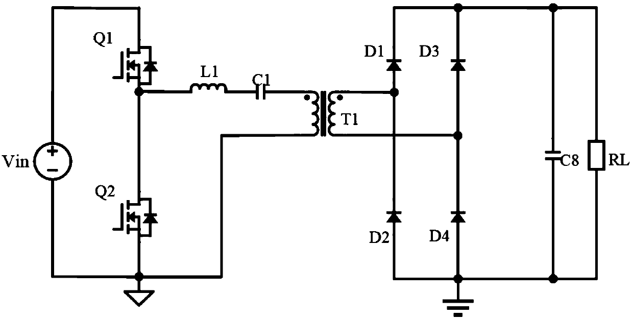
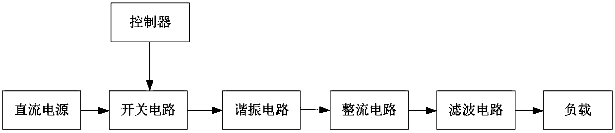
[0048] In order to solve the problems of limited output voltage range of constant power, discontinuous output voltage range, high cost, large volume, and inability to output zero voltage of current resonant converters, such as image 3 As shown, this embodiment provides a series-parallel seamless conversion resonant converter, which includes a DC power supply, a switch circuit, a resonant circuit, a rectifier circuit and a filter circuit that are electrically connected in sequence, and the output end of the filter circuit is also connected to a load; The circuit is controlled by an external controller; the resonance circuit includes a resonance module and a transformer module; the transformer module includes N transformers, the resonance module includes N groups of resonance groups, the switch circuit includes N groups of switch modules, N≥2 and N is an even number; the rectifier circuit includes a first rectifier module, a second rectifier module and a third rectifier module; ...

Embodiment 2

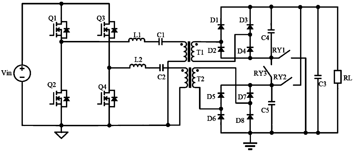
[0100] The difference between this embodiment and the first embodiment is that the switch module includes a full-bridge switch module. Compared with the half-bridge switch module, the full-bridge switch module is suitable for higher power occasions.

[0101] Among them, there are many ways to choose the full-bridge switch module, such as Figure 13 As shown, the full-bridge switch module includes a first switch transistor Q1, a second switch transistor Q2, a third switch transistor Q3 and a fourth switch transistor Q4; the conduction and closing of the first switch transistor Q1 to the fourth switch transistor Q4 are determined by the micro- The controller controls; the first end of the first switch tube Q1 is connected to the output end of the DC power supply, the second end of the first switch tube Q1 is connected to the first end of the second switch tube Q2, and the second end of the second switch tube Q2 is connected to The input end of the DC power supply, the second end...


PUM


Abstract

The invention provides a resonant converter with series-parallel seamless conversion, and belongs to the technical field of power electronics. The resonant converter comprises a DC power supply, a switching circuit, a resonance circuit, a rectifier circuit and a filter circuit which are sequentially electrically connected. The switching circuit is controlled by an external controller. The resonance circuit comprises a resonance module connected to the switching circuit and a transformer module connected to the resonance module. The transformer module comprises N transformers. The resonance module comprises N resonance sets. The switching circuit comprises N sets of switching modules, wherein N is no less than 2 and is even. The rectifier circuit includes a first rectifier module, a secondrectifier module and a third rectifier module. The resonant converter solves the problem that the existing resonant converter is limited in constant power output voltage range, discontinuous in outputvoltage range, high in cost, large in volume and incapable of outputting zero voltage.

Description

technical field [0001] The invention belongs to the technical field of power electronics, and in particular relates to a series-parallel seamless conversion resonant converter. Background technique [0002] At present, common resonant converters include series, parallel, and series-parallel resonant converters. Due to their simple circuit topology and their ability to achieve soft switching over the full load range, resonant converters are widely used in state-of-the-art power supplies that provide the highest power density and efficiency. Although the resonant converter has many advantages such as soft switching of switching devices, low switching loss, high efficiency, and superior EMI (Electromagnetic Interference) performance compared to hard switching, there are still obvious defects, such as figure 1 As shown, taking the current basic resonant converter as an example, the output voltage of the resonant converter is usually adjusted by adjusting the operating frequency...

Claims


Application Information

Patent Timeline
Patent Type & Authority Applications(China)
IPC IPC(8): H02M3/335
CPCH02M3/33584Y02B70/10
Inventor 李建山徐增新曾瑞龙岑央群徐利敏
Owner HANGZHOU ZHONGHEN ELECTRIC CO LTD
Why Eureka
Try Eureka