Aerodynamic shape and design method of two-way flying wing aircraft

A technology of aerodynamic shape and aircraft, applied in the direction of full-wing aircraft, aircraft parts, aircraft control, etc., can solve the problem of insufficient control ability of the shape of the rudder surface, and achieve the effect of solving the insufficient control ability, easy implementation, and simple design

Active Publication Date: 2020-12-25
BEIJING AEROSPACE TECH INST
View PDF5 Cites 0 Cited by
  • Summary
  • Abstract
  • Description
  • Claims
  • Application Information

AI Technical Summary

Problems solved by technology

[0004] The purpose of the present invention is to overcome the deficiencies in the prior art, provide a two-way flying wing aircraft aerodynamic shape and design method, and solve the problem of insufficient control ability of conventional rudder surface shape

Method used


Image

  • Aerodynamic shape and design method of two-way flying wing aircraft
  • Aerodynamic shape and design method of two-way flying wing aircraft
  • Aerodynamic shape and design method of two-way flying wing aircraft

Examples


Embodiment 1

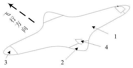
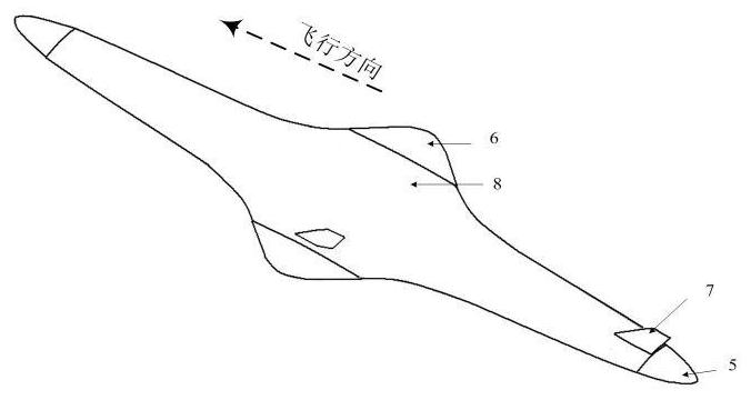
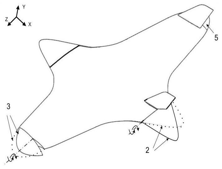
[0038] Embodiment 1, as figure 1 and figure 2 As shown, the present invention proposes an aerodynamic shape of a two-way flying wing aircraft, comprising a low-speed mode wing 1, a high-speed mode wing 8, a low-speed mode aileron 3, a high-speed mode aileron 6, and a low-speed mode elevator 2 , high-speed mode elevator 5, low-speed mode vertical tail 4 and high-speed mode vertical tail 7;

[0039] The high-speed mode wing 8 in the low-speed mode is the low-speed mode fuselage of the aircraft, the low-speed mode aileron 3 adopts the low-speed mode wing 1 without the high-speed mode elevator side wingtip as the full-motion control surface, and the low-speed mode elevator 2. The tail end of the low-speed mode fuselage is used as the rudder surface, and the low-speed mode vertical tail 4 is located on the symmetrical plane of the upper surface of the low-speed mode fuselage of the aircraft and before the low-speed mode elevator 2 .

[0040] The low-speed mode wing 1 in the high...

Embodiment 2

[0049] Embodiment 2, according to another aspect of the present invention, the present invention provides a kind of design method of aerodynamic profile of two-way flying-wing aircraft, and design method is as follows:

[0050] Determine the position of the low speed mode elevator, low speed mode aileron, high speed mode elevator and high speed mode aileron;

[0051] According to the longitudinal stability matching requirements of the aircraft in the low-speed mode and high-speed mode, the area of ​​the elevator rudder surface in the low-speed mode and the elevator rudder surface area in the high-speed mode of the aircraft are respectively designed. Cause problems such as excessive hinge torque, the deflection angle of the elevator is constrained by the non-failure of the rudder surface, the area of ​​the rudder surface of the low-speed mode elevator is 5% to 10% of the projected area of ​​the whole machine, and the maximum available deflection angle of the rudder surface is -3...


PUM


Abstract

The invention provides a bidirectional flying-wing aircraft aerodynamic layout and a design method. The bidirectional flying-wing aircraft aerodynamic layout comprises a low-speed modal wing, a high-speed modal wing, a low-speed modal aileron, a high-speed modal aileron, a low-speed modal elevator, a high-speed modal elevator, a low-speed modal vertical tail and a high-speed modal vertical tail, wherein the low-speed modal aileron adopts a low-speed modal wing tip as a full-motion control surface, the low-speed modal elevator adopts the tail end of a low-speed modal fuselage as a control surface, and the low-speed modal vertical tail is positioned on symmetrical surfaces of the upper surface of the low-speed modal fuselage of the aircraft and in front of the low-speed modal elevator; the high-speed modal aileron adopts a high-speed modal wing tip as a full-motion control surface, the high-speed modal elevator adopts the tail end of a high-speed modal fuselage as a control surface, andthe high-speed modal vertical tail is located on the symmetrical surfaces of the upper surface of the high-speed modal fuselage of the aircraft and located in front of the high-speed modal elevator. The problem that a conventional control surface layout is insufficient in control capacity is solved.

Description

technical field [0001] The invention relates to an aerodynamic shape of a two-way flying-wing aircraft, which belongs to the technical field of aircraft shape design. Background technique [0002] The aerodynamic layout of the new concept of two-way flying wing was proposed by Professor Chage Cheng of the University of Miami around 2009. The shape of the aircraft is approximately diamond-shaped, and it flies with a large aspect ratio shape at subsonic speed (low-speed mode). The vertical axis is rotated 90° to achieve high-speed flight (high-speed mode) with a small aspect ratio shape. With the help of large / small aspect ratio flight mode transitions, the requirements for aerodynamic layout in different speed ranges are met, and the aerodynamic performance of the aircraft in the full speed range is close to optimal. [0003] The research on the layout of the two-way flying wing is still in the exploratory stage, and the layout of the control rudder surface adopts the tradit...

Claims


Application Information

Patent Timeline
Patent Type & Authority Patents(China)
IPC IPC(8): B64C39/10B64C9/00
Inventor 刘晓斌朱国祥
Owner BEIJING AEROSPACE TECH INST
Why Eureka
Try Eureka