Oscillating fan

A technology of oscillating fans and fan components, which is applied to parts of pumping devices for elastic fluids, non-variable pumps, pump devices, etc., and can solve problems such as potential safety hazards, easy to fall when using, and unstable center of gravity of fans. Achieve the effect of lowering the center of gravity, convenient use and simple structure

Pending Publication Date: 2019-05-10
SHENZHEN ZAIWAN TECH CO LTD
View PDF0 Cites 2 Cited by
  • Summary
  • Abstract
  • Description
  • Claims
  • Application Information

AI Technical Summary

Problems solved by technology

However, the above-mentioned method of installing the motor on the fan assembly is only suitable for larger fans. For smaller fans, especially miniature

Method used


Image

  • Oscillating fan
  • Oscillating fan
  • Oscillating fan

Examples


Embodiment 1

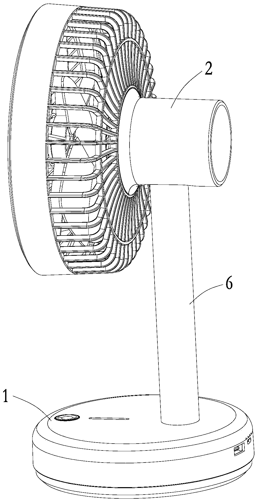
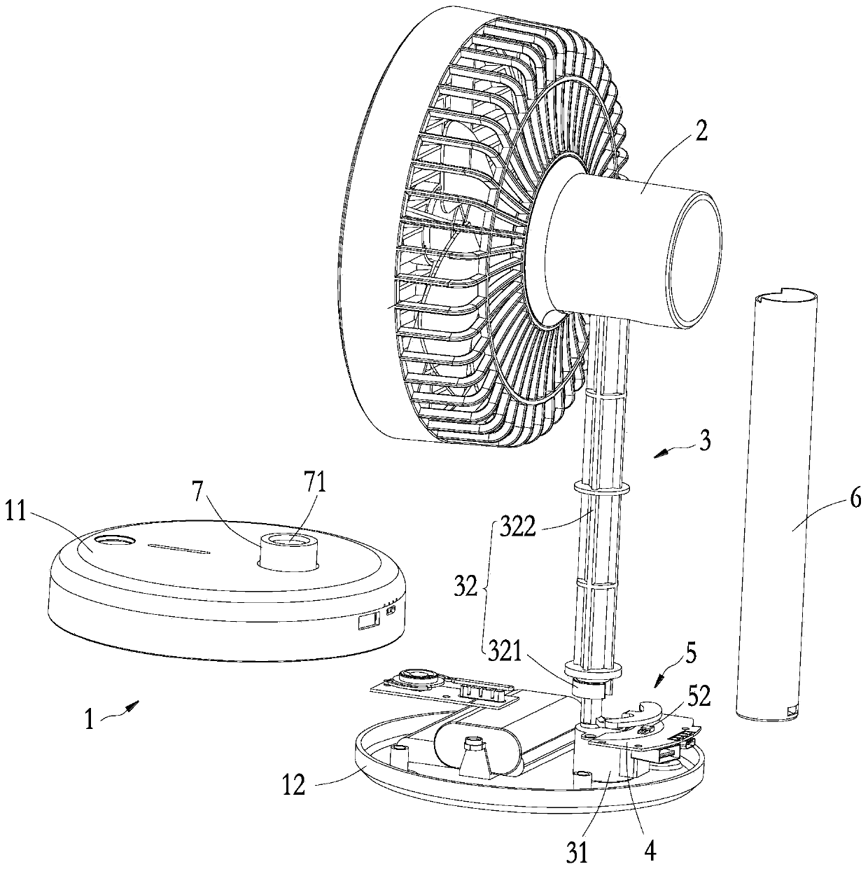
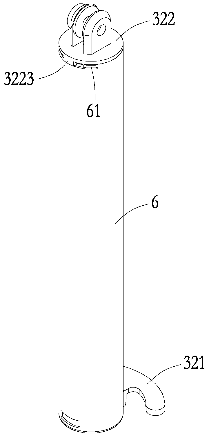
[0029] Such as Figure 1 to Figure 6 As shown, the first preferred embodiment of the present invention provides an oscillating fan, which includes a base 1 , a fan assembly 2 , an oscillating assembly 3 , a circuit assembly 4 , a reversing assembly 5 , a support pipe 6 and a connecting column 7 . The oscillating head assembly 3 includes a driver 31 installed in the base 1 , and a transmission mechanism 32 drivingly connected between the driver 31 and the fan assembly 2 . The transmission mechanism 32 includes a connection part 321 and a transmission part 322 , and the driver 31 , the connection part 321 , the transmission part 322 and the fan assembly 2 are sequentially connected in transmission. The support tube 6 is sheathed on the outside of the transmission member 322 and slides against the transmission member 322 . The reversing assembly 5 is installed in the base 1 and cooperates with the driver 31 to adjust the rotation direction of the fan assembly 2 . In this embodi...

Embodiment 2

[0043] Such as Figure 7 , Figure 8 as well as Figure 9 As shown, the second preferred embodiment of the present invention provides an oscillating fan, which includes a base 1 , a fan assembly 2 , an oscillating assembly 3 , a circuit assembly 4 , a reversing assembly 5 , a support pipe 6 and a connecting column 7 . The difference from the first embodiment lies in the structure of the moving head assembly 3 , the support pipe 6 and the connecting column 7 . In this embodiment, the connecting piece 321 in the oscillating head assembly 3 includes a connecting body 3211, a reversing arm 3212 protruding from the side of the connecting body 3211, and a first clamping part 3213 provided at the end of the connecting body 2412. The connecting portion 3213 is a buckle provided on the annular wall. The buckle fits with a through hole (not numbered) provided in the first buckling part 32131 of the connection body 3211 , and the buckle and the through hole are inserted into each othe...


PUM


Abstract

The invention discloses an oscillating fan which comprises a base, a fan assembly, an oscillating assembly driving the fan assembly to rotate relative to the base, and a circuit assembly connected with the oscillating assembly, wherein the oscillating assembly comprises a driver mounted in the base and a transmission mechanism rotatably connected between the driver and the fan assembly; the transmission mechanism comprises a connecting piece and a transmission piece; and the driver, the connecting piece, the transmission piece and the fan assembly are in transmission connection sequentially. The oscillating fan has the following benefits: the driver is arranged in the base, so that the center of gravity of the oscillating fan is lowered, and the using smoothness and reliability of the oscillating fan are improved; in addition, the driver drives the fan assembly to rotate relative to the base through the connecting piece and the transmission piece, and the transmission piece can also support the fan assembly; and moreover, the oscillating fan is simple in structure and convenient to use.

Description

technical field [0001] The present invention relates to the field of fans, more specifically, to an oscillating fan. Background technique [0002] A fan is a common electronic product. When the weather is hot, people usually use the fan to cool down. During use, when people need to change the direction of the wind blown by the fan, there are usually two structures for changing the blowing direction of the fan. One is to set the fan head as an oscillating head to switch the position of the fan head to realize the effect of changing the wind direction, and the other is to set a rotatable wind guide cover at the position of the fan outlet. [0003] In the prior art, an oscillating fan includes a base, a fan assembly, and an oscillating assembly for driving the fan assembly to rotate relative to the base. Most of the oscillating head assemblies use a motor at the connection position with the fan assembly, and the rotation of the motor drives the fan assembly to swing, so as to...

Claims


Application Information

Patent Timeline
IPC IPC(8): F04D25/10F04D29/00
Inventor 陈丽芳
Owner SHENZHEN ZAIWAN TECH CO LTD
Why Eureka
Try Eureka